Online remote control of PPU pipelines - an effective means of control or a useless application? Connecting remote lighting control.
Remote control
a method for detecting violations of a protected area of a GG (water area, object) using SC (systems) and instruments. D.k. It is also carried out in order to check the operability (serviceability) of the SC (system) and devices, carried out by the communications and alarm duty officer (outpost duty officer), as well as by the border guard directly at the protected area of the GG. Results D.k. are entered in a special journal.
Border Dictionary. - M.: Academy of the Federal PS of the Russian Federation. 2002 .
See what “Remote control” is in other dictionaries:
remote control- (ITU T Y.1314). Topics: telecommunications, basic concepts EN remote monitoringRMON...
remote control (object condition)- [Intent] EN remote monitoring… Technical Translator's Guide
remote control of network operation- - Telecommunications topics, basic concepts EN remote network monitoringRMON ... Technical Translator's Guide
remote collection of administrative information- environment for remote control of the network remote control remote monitoring - [L.G. Sumenko. English-Russian dictionary on information technology. M.: State Enterprise TsNIIS, 2003.] Topics information Technology in general Synonyms environment... ... Technical Translator's Guide
remote- oh, oh. distance f. 1. Rel. to a distance (distance), produced, acting at a distance. Remote measurements. Remote control. BAS 2. ♦ Remote bomb, grenade. Bomb, grenade exploding in the air. BAS 2. Romanian... ... Historical Dictionary of Gallicisms of the Russian Language
remote controller for water heating boiler- (provides continuous monitoring and regulation of the main parameters and heating modes of the boiler) [A.S. Goldberg. English-Russian energy dictionary. 2006] Energy topics in general EN hot water boiler remote control ... Technical Translator's Guide
remote- 4.1.3 remote (wireless) control. Source: GOST R ISO 21467 2011: Earth-moving machines. Machines for…
GOST R 53698-2009: Non-destructive testing. Thermal methods. Terms and definitions- Terminology GOST R 53698 2009: Non-destructive testing. Thermal methods. Terms and definitions original document: 2.2.1 active method of thermal non-destructive testing; active method: A method of thermal non-destructive testing in which the object ... Dictionary-reference book of terms of normative and technical documentation
GOST 25314-82: Non-destructive thermal control. Terms and definitions- Terminology GOST 25314 82: Non-destructive thermal control. Terms and definitions original document: 14. Active method thermal non-destructive testing Active method Thermal non-destructive testing method, in which the test object... ... Dictionary-reference book of terms of normative and technical documentation
GOST 27452-87: Radiation safety monitoring equipment at nuclear power plants. General technical requirements- Terminology GOST 27452 87: Radiation safety monitoring equipment at nuclear power plants. General technical requirements original document: Radiation emergency Radiation situation corresponding to unexpected significant... ... Dictionary-reference book of terms of normative and technical documentation
Books
- Remote forecast of kimberlite magmatism, Serokurov Yu.N., Kalmykov V.D., Zuev V.M.. The work briefly characterizes the objects of forecast and search, views on their structural control. A technology has been proposed that makes it possible to delineate the development areas of the known kimberlite…
Page 1
A remote control and production management system in a machine shop allows one dispatcher to monitor the entire production process using communication and signaling equipment. A similar centralized control system in the forging and pressing shop allows the dispatcher to control the use of presses, observe the entire operating cycle of thermal furnaces, and a television installation allows the dispatcher to monitor the operation of the workshop transport.
Remote monitoring systems at oil refineries and petrochemical plants have the most wide application. The distance for transmitting readings usually does not exceed 300 m, which turns out to be quite sufficient. To transmit measurement results over a distance of several tens of kilometers (and sometimes hundreds), telemeasurement systems are used. In such systems, the measurement result using a converter (sensor) is converted into coded, usually discrete signals transmitted over the appropriate communication channel. In a secondary device installed at the other end of the communication channel, these signals are converted and recorded in digital or analog form.
Systems for remote monitoring of technological parameters allow you to centralize the control of technological processes. When secondary instruments of remote control systems of any production process are placed in one place, the personnel on duty (operators) are freed from the need to be in constant motion around the production area or installation to take readings from instruments and make adjustments to the process.
More common are remote monitoring systems in which the measured parameter is converted into a physical quantity that is more convenient for transmission over a distance. With this method, the distance between the measuring device and the actuator can reach 3 km, and the signals are transmitted via communication lines.
There are several local and remote control systems. A local system is obtained by installing instruments directly on the facility’s units or next to them, and a remote system is obtained by using instruments with devices for transmitting readings over a distance. If the information arrives at the central panel, where the reading devices of all monitored parameters are concentrated, then the system is called centralized. These systems usually operate automatically, without direct and continuous intervention by operating personnel.
Pipeline companies use remote monitoring and control systems in various combinations and with to varying degrees automation.
When drilling fluid enters the choke manifold, the remote pressure control system begins to operate at the control panel located on the floor of the drilling rig. The drilling choke operates in the following positions: fully open - the solution flow flows freely; not completely open - the solution flow is adjustable; the nozzle is completely closed - the flow movement is blocked. Once the flow of drilling fluid enters the choke, it is throttled through the annular flow area between the tip and the nozzle seat.
Therefore, it seems more correct to use thermistors in remote temperature control systems not as temperature sensors, but as alarm sensors of certain temperature limits (permissible for the controlled environment). Therefore, if the thermistors in the installation are damaged or worn out, it is necessary to re-adjust the equipment and recalibrate the receiving devices. It is clear that this operation is easier to perform for two points than for the entire scale as a whole.
One of the main parts of pipeline operational diagnostics is the remote monitoring system. The principle of constructing remote control is based on a multifactorial analysis of the results of centralized collection and processing of information on a computer: the main characteristics of the metal and its continuity both in time and depending on periodically switched on or continuously operating sensors of an extensive control network. Correlation analysis of data on the dynamics of metal properties and continuity, taking into account extrapolation of trends, makes it possible to predict the reliable operation of pipeline elements in the short and long term. Methods and means of periodic monitoring are selected taking into account the diagnosis of certain elements of the oil pipeline, as well as based on criteria that ensure reliability and efficiency requirements.
| Block diagram of the remote control system. PP - primary converter. VP - secondary device (other designations are in the caption). |
The diagram of the remote control system is shown in Fig. 1.5. Remote control systems with signal transmission in the form of compressed air pressure have found wide application in chemical, petrochemical and mineral fertilizer industries. At the same time, the distance between the primary and secondary devices reaches 300 m, which is quite enough to centralize the control of objects within one production or one technological installation. Remote systems allow you to monitor the operation of equipment and the progress of the production process from one place - the operator’s room. Typically, a control panel is installed in this room, on which secondary devices are placed.
Compressor stations with three or more machines must be equipped with a system of remote monitoring and signaling of the operation of installations with the following instrumentation installed on each compressor: devices for remote monitoring of temperature and pressure of air, water and oil, as well as devices indicating deviation of the compressor operation from normal regime according to these parameters; devices that automatically turn off the compressor when the pressure and temperature of the compressed air increases, as well as when the supply of cooling water is stopped.
To determine the operating mode of wells, automated remote control systems must be provided in the fields.
Nikki Bishop – [email protected], Aaron Crews - [email protected]
Automated monitoring of key process assets improves the reliability of production equipment and reduces maintenance costs. Remote monitoring provides instant alerts, remote diagnostics, and 24/7 monitoring of key process assets.
The development of communication technologies in recent years has made it possible to instantly connect with anyone almost anywhere in the world. These technologies can also be used on the factory floor to enable equipment located there to communicate its status to personnel. Now production assets can “talk” to the control room. Moreover, the right person will receive an alert exactly when the equipment needs attention.
But before moving on to a discussion of remote monitoring, it is necessary to consider how to choose the most effective strategy control of technological assets. The right automated monitoring strategy is the foundation on which an effective remote monitoring infrastructure is built (Figure 1).

Rice. 1. Automated control allows you to accurately and efficiently plan repairs
It is no secret that the correct preventive strategy maintenance Improves overall reliability and helps achieve established production availability targets. However, not all preventative maintenance strategies produce the same results. Predictive maintenance, which relies on periodic and perhaps infrequent data collection, does not provide complete, real-time information about asset health. Periodic data can come from “tablet walks,” where employees go to equipment locations at regular intervals to manually collect data. This can happen once a shift, once a day, or maybe even less often.
This method provides only a “snapshot” of equipment health data, and early warning of impending problems may not occur. Moreover, sending employees to manually collect data into areas where equipment is operated may pose a safety risk.
With little or no understanding of which production assets actually need attention, resources may be wasted on servicing equipment that does not need it. Research has shown that more than 60% of routine instrumentation inspection visits by technicians either result in no action or result in minor configuration changes that could have been completed without an on-site visit.
Secrets of Effective Maintenance
Automated monitoring provides real-time indication of the health of production assets and allows you to identify process conditions that could unintentionally or without the knowledge of personnel lead to equipment failure. Operators make adjustments to the operation of process-related equipment to avoid failure. With a strong warning system in place, maintenance personnel can work on the equipment that actually needs it, rather than wasting time searching for problems with manual inspections.
Assessing the importance of a particular technological asset often determines the management approach. While real-time monitoring (and protection) of critical equipment such as large compressors or turbines is common practice on many manufacturing sites, online monitoring of second-tier equipment such as pumps, heat exchangers, fan units, small compressors, cooling towers and Air-cooled heat exchangers (with fans and fins) have traditionally been considered too expensive to implement or too complex. Even though these unmonitored or manually monitored assets may not be initially classified as “critical,” their failure or malfunction can result in significant process disruption or shutdown. The result is downtime and increased workload on production site personnel, who will be forced to engage in unscheduled emergency repairs. Such assets can be called “key technology assets” (Fig. 2).

Rice. 2. Key assets usually do not have control systems already in place, but the consequences of their failure can be serious
Real-time monitoring solutions improve their overall reliability while reducing maintenance costs.
Components of effective control of technological assets
Monitoring technology assets is about more than just collecting data (Figure 3). Gathering information first lays the foundation for an asset control strategy. You can use existing measurement tools or easily add new wireless measurement channels. Once the measurement infrastructure is in place, pre-designed monitoring solutions (plug and play) take the raw data and, through analysis, transform it into meaningful warning signals. Process and asset data can be combined to identify conditions that can lead to equipment failure. It is possible to adjust the process conditions in such a way as to completely eliminate similar look refusals.

Rice. 3. Data collection is not enough for effective control. For a program to be successful, a combination of data collection, analysis, awareness and action is required
Alerts generated by analyzing and combining data are only useful if they reach the intended employees in a timely manner. Organization of the information process is a very important component of the automated control system. Such awareness can be achieved in different ways, the most effective of which is automatic notification. Alerts in the form of text messages or email ensure that information reaches the right person immediately.
After the warning signal is accepted, the responsible employee begins to solve the problems that have arisen. Remote access via a tablet computer or smartphone allows you to diagnose and take action almost instantly. If necessary, you can notify specialized specialists who can also log into the system remotely and assist in diagnosing the problem. Thanks to the automated notification system, it is also possible to periodically generate and distribute reports. These reports can include trends that show changes in asset availability, which can help you see deteriorating performance and prevent impending failure.
Thus, automated monitoring combined with automatically generated warning signals and the possibility of remote access represents powerful tool monitoring the operational characteristics of technological assets.
Critical production assets and remote monitoring in action
One site that has realized the benefits of remote monitoring of technology assets is the J. J. Pickle Research Campus at the University of Texas at Austin (USA). It is home to the Separations research program, which involves industry and academics. The program conducts fundamental research for chemical, biotechnology, oil and gas processing, pharmaceutical and food companies.
Currently one of Separations' research projects is the removal carbon dioxide from flue gases. This process includes absorption and stripping columns and associated equipment such as pumps, fans and heat exchangers. The technological process does not imply equipment redundancy, so it is important to establish its proper maintenance and support in working condition. The loss of one element means stopping the entire technological process until the repair is completed.
To reduce the risk of unplanned downtime, critical asset control strategies for pumps, heat exchangers and fans were successfully implemented. Now personnel receive information about the performance of production assets in real time and control the conditions of the technological process (Fig. 4). When they become such that they can cause deterioration in equipment performance, corrective action is taken to prevent further damage or failure. For example, increasing vibration warning signals indicate impending failures and provide time for maintenance to be carried out before such failures occur.

Rice. 4. Wireless vibration sensor installed on the pump provides valuable data to the automated control system
To ensure timely warnings are communicated to the correct personnel, University of Texas scientists have gone one step further by creating a remote monitoring infrastructure. Alerts for events such as heat exchanger fouling, resonant speed detection, hydrocarbon leakage and pump cavitation can be automatically sent to on-site personnel as well as to remote experts (highly specialized, experienced technicians) when the failure condition is just beginning to manifest itself. myself.
In addition to monitoring process equipment, a remote monitoring system known as an Intelligent Operations Center (iOps) system checks the health of the control system and provides warnings such as an overloaded PC or a failed backup controller. These alerts can be sent automatically by text message or to email. Through a remote connection, experts can remotely assist in diagnosing equipment problems and help implement appropriate corrective actions. They can log in using secure access to a virtual private network. When accessing the system using a tablet or smartphone, diagnostic functions are instantly available.
Using a remote monitoring infrastructure, reports can be generated periodically according to customer needs and sent automatically. These reports contain trends in the health of technology assets and systems and clearly indicate which equipment or systems require attention. At the University of Texas, remote experts are equipped with information and ready to take action when problems arise. unfavorable conditions, be it cavitation in the pump or PC overload. This can be called automated remote control.
In Fig. Figure 5 shows the remote monitoring process implemented at the University of Texas. In the center of the picture is a production plant and a control room with operators. Control strategies are implemented for pumps, heat exchangers and fans, and these solutions use data from operating equipment to generate warning signals and transmit them to the control room. But what happens if the operator is not in the control room or is distracted from the screen? Even if the operator is not on site, the iOps center is able to monitor any alarms around the clock through installed remote monitoring tools.

Rice. 5. Automated remote monitoring process implemented at the University of Texas
If there is a problem with a pump, such as cavitation, the key process asset monitoring system will detect it by collecting, integrating and analyzing equipment and process data. The warning signal and equipment health percentage information will be sent to the remote monitoring device and then to the iOps center, after which the center contacts the local service at the site, and, if necessary, a remote expert. An expert logs in, diagnoses the problem, and suggests corrective measures. They work with the local service to determine what needs to be done, and then the operator in Austin takes corrective action and fixes the problem before it becomes a failure. This method ensures that the malfunction will not go unnoticed and problems will be resolved quickly and efficiently.
* * *
When using the latest achievements In the field of wireless systems and communication technologies, the era of remote online monitoring of production equipment is becoming a reality. Wireless technologies make it easy and cost-effective to add missing measurement channels to key process assets. Control systems operate as Plug&Play and provide simple data collection and analysis. Remote monitoring and automated alarms ensure that signals generated by monitoring systems are not lost and corrective actions are taken before unplanned downtime due to equipment failure occurs.
More detailed information about the management of enterprise technological assets and the management system is posted on the website www.emersonprocess.com/ru/DeltaV .
Emerson Process Management, one of Emerson's divisions, works in the field of automation technological processes production for various industries. The company develops and produces innovative products and technologies, consults, designs, provides project management and service for maximum efficient work enterprises.
Purpose
The operational remote monitoring system (ORMS) is designed to continuously monitor the condition of the thermal insulation layer of polyurethane foam (PUF) of pre-insulated pipelines throughout their entire service life. SODK is one of the main tools for the maintenance of pipelines built using the “pipe-in-pipe” technology using signal copper conductors. The SODK complex of instruments and equipment makes it possible to locate damage locations in a timely manner and with great accuracy. The use of SODK contributes to the safe operation of pipeline systems and can significantly reduce costs and time for repair work.
Operating principle and system organization
The control system is based on the use of an insulation moisture sensor distributed along the entire length of the pipeline. Signal copper conductors (at least two), located in the heat-insulating layer of each pipeline element, are connected along the entire length of the branched pipeline network into a two-wire line, combined at the end elements into a single loop. Conductors of any branches are included in the break of the signal conductor of the main pipeline. This loop of copper signal conductors, the steel pipe of all pipeline elements and the thermal insulation layer of rigid polyurethane foam between them form the insulation moisture sensor. Electrical and wave properties This sensor allows you to:
1. Monitor the length of the humidification sensor or the length of the signal loop and, as a consequence, the length of the pipeline section covered by this sensor.
2. Monitor the humidity state of the heat-insulating layer of the pipeline section covered by this sensor.
3. Search for places where the heat-insulating layer is moistened or where the signal wire is broken in the section of the pipeline covered by this sensor.
Monitoring the length of the humidification sensor is necessary to obtain reliable information about the state of humidity of the heat-insulating layer along the entire length of the pipeline section covered by this sensor. The length of the signal loop (the length of the humidification sensor) is determined as the ratio of the total resistance of the signal conductors connected in a closed circuit to their specific resistance. The length of the pipeline section covered by this sensor is half.
When monitoring the humidity state, the principle of measuring the electrical conductivity of the heat-insulating layer is used. With increasing humidity, the electrical conductivity of thermal insulation increases and the insulation resistance decreases. An increase in the humidity of the thermal insulation layer can be caused by leakage of coolant from a steel pipeline or penetration of moisture through the outer shell of the pipeline.
The search for damage sites is carried out on the principle of pulse reflection (pulse reflectometry method). Moistening of the insulating layer or a wire break leads to a change in the wave characteristics of the insulation moistening sensor in specific local areas. The essence of the reflected pulse method is to probe a line of signal conductors with high-frequency pulses. Determining the delay between the time of sending probing pulses and the time of receiving pulses reflected from inhomogeneities of wave impedances (wet insulation or damage to signal conductors) allows you to calculate the distances to these inhomogeneities.
For operational work with the insulation moisture sensor, the signal conductors and the “mass” of the steel pipe body are removed from the heat-insulating layer. These outputs are organized using special pipeline elements in which the signal conductors are output by a cable passing through the external insulation using a sealing device. These cables, led out into technological rooms, ground or wall carpets, together with the terminals connected to them, form control and switching points along the route - technological measuring points.
There are different end and intermediate measuring technological points.
Pipeline end elements with cable outlets are used at end measuring points. Cables from the supply and return pipes are connected to the end terminal installed in technological rooms or structures, ground or wall carpets.
At intermediate points, pipeline elements with an intermediate cable outlet are usually used. Cables from both pipelines are brought out into the ground carpet or technological structures and connected to an intermediate or double end terminal. But in places where thermal insulation is broken (in a thermal chamber, etc.), the organization of an intermediate measuring point is carried out using end elements with cable leads. Cables from all pipeline elements are led out into the ground carpet or technological structure and connected to the appropriate terminal.
Technological measuring points installed at certain distances make it possible to quickly carry out exploratory measurements with sufficient accuracy.
Equipment composition
The control system is divided into the following parts: pipe, signal and additional devices.
The pipe part is all the pipeline elements and components that directly form the insulation moisture sensor:
- Pipe components with two or more copper signal conductors.
- Intermediate and end cable terminals.
- Pipeline end elements.
- Installation and connection kits for connecting signal conductors when waterproofing joints and for extending cable outlets.
Pipe components with two or more copper signal conductors include pre-insulated pipes, bends, expansion joints, tees, ball valves, etc.
Signal conductors installed inside the polyurethane foam insulation of each element are located parallel to the steel heat-carrying pipe at a distance of 16÷25 mm. from her. When assembling pipes, the conductors are fixed in polyethylene sheath centralizers, which are installed at a distance of 0.8÷1.2 m from each other. These conductors are made of copper wire with a cross section of 1.5 mm 2 (grade MM 1.5).
In all elements, the control system wires are located in the “ten minutes to two o’clock” position.
The end cable outlet is installed at the end of the thermal insulation. Structurally, it can be performed in two versions.
The first option is a pipeline end element with a cable outlet and a metal insulation plug (ZIM KV). In this element, two wires of a three-core cable are connected to the signal conductors at the end of the pipe, the third wire is connected to the steel pipe, and the cable is exited through a sealing device mounted on the insulation plug. This option is used to route signal conductors inside engineering structures and technological premises.

The second option is a pipeline end element with a metal insulation plug and a cable outlet (KV ZIM). In this element, two wires of a three-core cable are connected to the break of the main signal wire, the third wire is connected to the steel pipe, and the cable is brought out through a sealing device installed on the pipe shell. This option is used to route signal conductors into special technological devices (carpets) installed outside engineering structures and buildings.

Intermediate cable outlets are designed to divide an extensive pipeline network into sections of a certain length, which provides the necessary accuracy when troubleshooting the control system. They are installed along the length of the route at distances determined by regulatory documentation (SP 41-105-2002) and agreed upon with the operating organizations. The intermediate cable outlet is made in the form of a special pipeline element, in which four wires of a five-core cable are connected to the break of the signal wires, the fifth wire is connected to the working pipe, and the cable itself is brought out through a sealing device installed on the pipe shell.
The end elements of the pipeline are installed at the end of the thermal insulation and are designed to combine a two-wire line into a single loop and protect the thermal insulation layer from moisture penetration. The connection of the signal conductors to each other at the end elements of the pipeline is made at the end of the insulating layer under the insulation plug.

The insulation resistance of each signal conductor of any element is at least 10 MΩ.
Installation and connection kits
 The SODK wire connection kit (included in the kits of materials for sealing butt joints) is designed to connect the SODK wires and fix them on the heat-carrying pipe at a certain distance from it.
Delivery set for 1 joint:
- wire holder - 2 pcs.
- crimp coupling for connecting wires - 2 pcs.
- solder, quantity per 1 joint - 2g
- flux or solder paste - 1g
- tape with adhesive layer - according to the table:
| Outer diameter of steel pipe | Consumption of tape with adhesive layer per 1 joint |
| d, mm | m |
| 57 | 0,5 |
| 76 | 0,7 |
| 89 | 0,85 |
| 108 | 1,02 |
| 133 | 1,26 |
| 159 | 1,5 |
| 219 | 2,1 |
| 273 | 2,6 |
| 325 | 3,1 |
| 377 | 3,55 |
| 426 | 4,05 |
| 530 | 5,02 |
The three-core output cable extension kit is used to extend the three-core cable of the UEC system at the end cable terminals during pipeline installation.
Scope of delivery:
Three-core cable - 5 m;
Heat shrink tube with a diameter of 25 mm L= 0.12 m;
Tape mastic "Gerlen" - 0.2 m2;
Electrical tape - 1 roll for 10 sets;
Crimp coupling for connecting wires - 3 pcs;
Heat-shrink tube with a diameter of 6 mm L= 3cm - 3 pcs;
Consumables (not included in delivery):
Solder - 3g.
- flux or solder paste - 1.5 g.
Five-core cable extension kit output used to extend the five-core cable of the UEC system at the intermediate cable outlet during pipeline installation.
Scope of delivery:
Five-core cable - 5 m;
Heat shrink tube with diameters of 25 mm - 0.12 m;
Tape mastic "Guerlain" - 0.2 m2;
Electrical tape - 1 roll 1 - 8 sets;
Crimp sleeve for splicing wires - 5 pcs.
Heat shrink tube with a diameter of 6 mm L= 3cm - 5 pcs.
Consumables (not included in delivery):
Solder - 5g.
- flux or solder paste - 2.5 g.
Signal part consists of interface elements and devices:
- Measuring and switching terminals for connecting devices at control and switching points of signal conductors.
- Monitoring devices (detectors, indicators) portable and stationary.
- Fault locating devices (pulse reflectometer).
- Measuring instruments (insulation tester, megger, ohmmeter).
- Cables for installation connection of terminals and connection of terminals with stationary control devices.
To switch signal conductors and connect devices to connecting cables at control and switching points, special switching boxes - terminals are used.
Terminals are divided into two main types: measuring and sealed.
Measuring The terminals are designed for prompt switching of signal conductors during measurements. The necessary switching and measurements are made using external plug connectors, without opening the terminal. Terminals of this type are installed in dry or well-ventilated engineering devices (ground or wall carpets, etc.) and technological rooms (central heating substation, electrical substation, etc.).
Sealed The terminals are designed for switching signal conductors in conditions of high humidity. The necessary switching and measurements are made using connectors installed inside the terminals. Access to them requires removal of the terminal cover. Terminals of this type can be installed in any technological devices (ground or wall carpets, etc.), structures and premises (in thermal chambers, in the basements of houses, etc.)
Types of measuring terminals:
End terminal (KT-11, KIT, KSP 10-2 and TKI, TKIM) - installed at control points at the ends of the pipeline;
End terminal with output to a stationary detector (KT-15, KT-14, IT-15, IT-14, KDT, KDT2, KSP 12-5 and TKD) - installed at the end of the pipeline, at the control point where connection to a stationary detector is provided ;
Intermediate terminal (KT-12/Sh, IT-12/Sh, PIT, KSP 10-3, TPI and TPIM) - installed at intermediate pipeline control points and at control points at the beginning of side branches.
Double end terminal (KT-12/Sh, IT-12/Sh, DKIT, KSP 10-4 and TDKI) - installed at the control point on the boundary of separation of control systems of associated projects;
Types of Sealed Terminals:
The end terminal is sealed - installed at control points at the ends of the pipeline;
Intermediate terminal (KT-12, IT-12, PGT and TPG) - installed at intermediate pipeline control points and at control points at the beginning of side branches.
Sealed connecting terminal (KT-16, IT-16, OT6, OT4, OT3, KSP 13-3, KSP 12-3, TO-3 and TO-4) - installed at those control points where it is necessary to combine several pipeline sections or several separate pipelines;
A sealed connecting terminal with access to a stationary detector (KT-16, IT-16, OT6, OT3, KSP 13-3, KSP 12-3 and TO-3) - installed at the control point where it is necessary to combine several separate pipelines into a single loop , and which provides for connecting a cable from a stationary detector;
Sealed pass-through terminal (KT-15, IT-15, PT, KSP 12 and TP) - installed in places where polyurethane foam insulation breaks (in thermal chambers, in the basements of houses, etc.) for switching connecting cables or installing an additional control point when the need to use long connecting cables.
Compliance of terminals produced by NPK VECTOR, LLC TERMOLINE, NPO STROPOLYMER, JSC MOSFLOWLINE and terminals of the TermoVita series
| OOO "TERMOLINE" | NPK "VECTOR" | NGO "STROYPOLYMER" | JSC "MOSFLOWLINE" | |
| KT-11 | IT-11 | WHALE | KSP 10-2 | End terminal. |
| KT-12 | IT-12 | PGT | No | ---- |
| KT-12/Sh | IT-12/Sh | PETE, DKIT | KSP 10-3, KSP 10-4 | Intermediate terminal, double end terminal |
| KT-13 | IT-13 | KGT | KSP 10 | ---- |
| KT-15 | IT-15 | KDT | KSP 12-5 | Terminal with output to detector |
| KT-14 | IT-14 |
KDT2 | KSP 12-5 (2 pieces) | Terminal with output to detector (2 pieces) |
| KT-15 | IT-15 | PT, OT4 | KSP 12 | Passage terminal |
| KT-15/Sh | IT-15/Sh | KIT4 | KSP 12-2, KSP 12-4 | ---- |
| KT-16 | IT-16 | OT6, OT3 (2 pieces) | KSP 13-3, KSP 12-3 (2 pieces) | __ |
The terminals are connected to the UEC conductors using connecting cables: a 3-core cable (NYM 3x1.5) for connecting terminals at the end sections of the heating main and a 5-core cable (NYM 5x1.5) for connecting terminals at intermediate sections of the heating main. Connection and operation of the terminals is carried out in accordance with the technical documentation of the manufacturer.
Control devices
Monitoring the condition of the UEC system during pipeline operation is carried out using a device called detector. This device records the electrical conductivity of the heat-insulating layer. When water gets into the thermal insulation layer, its conductivity increases and this is recorded by the detector. At the same time, the detector measures the resistance of conductors connected in a closed circuit.
Detectors can be powered from a 220 Volt network (stationary), or from an autonomous 9 Volt power source (portable).
Stationary detector allows you to simultaneously monitor two pipes with a maximum length of 2.5 to 5 km each, depending on the model.
Table 1
Technical characteristics of stationary detectors
| Options | Vector-2000 | PIKKON | SD-M2 | |||
| DPS-2A | DPS-2AM | DPS-4A | DPS-4AM | |||
| Supply voltage, V | 220 (+10-15)% | 220 (+10-15)% | 220 (+10-15)% | |||
| Number of controlled pipeline sections, pcs. | from 1 to 4 | 2 | 4 | 2 | ||
| up to 2500 | up to 2500 | 5000 | ||||
| more than 600 | more than 200 | more than 150 | ||||
| Insulation wetness indication, kOhm | less than 5 (+10%) | less than 5 (+10%) | Multi-level more than 100 from 30 to 100 from 10 to 30 from 3 to 10 less than 3 | |||
| 10 DC | 8 Direct current | 4 Alternating current | ||||
| 30 | 30 | 120 (2 tu.) | ||||
| Operating ambient temperature, С˚ | -45 - +50 | -45 - +50 | -45 - +50 | -40 - +55 | ||
| no more than 98 (25 °C) | 45÷75 | 45÷75 | No data | |||
| Protection class from external influences | IP 55 | IP 55 | IP 67 | |||
| Overall dimensions, mm | 145x220x75 | 170x155x65 | 220x175x65 | 180x180x60 | ||
| Weight, kg | no more than 1 | no more than 0.7 | no more than 1 | 0,75 | ||
When using a stationary detector SD-M2, it is possible to organize a centralized SODC of a branched heating network of considerable length (up to 5 km) from a single control center. For this purpose, the stationary detector has galvanically isolated contacts for each channel, which close when a malfunction occurs.
Connection and operation of stationary detectors is carried out in accordance with the technical documentation of the manufacturer.
The portable detector allows you to monitor a pipe with a maximum length of 2 to 5 km, depending on the model. One detector can control different areas pipelines that are not interconnected in unified system. The portable detector is not permanently installed at the site, but is connected to the controlled area by the employee conducting the inspection as part of its operation.
Table 2
Technical characteristics of portable detectors
| Options | Vector-2000 | PIKKON DPP-A | PIKKON DPP-AM | DA-M2 |
| Supply voltage, V | 9 | 9 | 9 | |
| Length of one controlled section of the pipeline, m | up to 2000 | up to 2000 |
5000 | |
| Indication of signal wire damage, Ohm | more than 600(+10%) | more than 200(+10%) | 150 | |
| Test voltage on signal wires, V | 10 DC | 8 Direct current | 4 Alternating current | |
| Indication of wetness of PPU insulation, kOhm | less than 5 (+10%) | less than 5 (+10%) | Multi-level more than 1000 from 500 to 1000 from 100 to 500 from 50 to 100 from 5 to 50 | Multi-level more than 100 from 30 to 100 from 10 to 30 from 3 to 10 less than 3 |
| Current consumption in operating mode, mA | 1,5 | 1,5 | No more than 20 | |
| Operating ambient temperature, "WITH | -45 - +50 | -45 - +50 | -20 - +40 | |
| Operating ambient humidity, % | no more than 98 (25 °C) | 45÷75 | Splashproof | |
| Overall dimensions, mm | 70x135x24 | 70x135x24 | 135x70x25 | |
| Weight, g | no more than 100 | no more than 170 | 150 | |
Connection and operation of portable detectors is carried out in accordance with the technical documentation of the manufacturer.
Damage detection devices
Used to determine the location of damage pulse reflectometer, providing acceptable measurement accuracy. The reflectometer allows you to determine damage at distances from 2 to 10 km, depending on the model used. The measurement error is approximately 1-2% of the length of the measured line. The accuracy of measurements is determined not by the error of reflectometers, but by the error of the wave characteristics of all pipeline elements (wave impedance of the insulation moisture sensor). Depending on the amount of insulation moisture, the reflectometer allows you to determine the location of several places with reduced insulation resistance.
Technical characteristics of domestic pulse reflectometers
| Name | FLIGHT-105 | FLIGHT-205 | RI-10M | RI-20M |
| Manufacturing plant | NPP "STELL", Bryansk | JSC "ERSTED", St. Petersburg | ||
| Measuring distance range | 12.5 -25600 m |
12.5-102400m | 1- 20000 m | 1m-50km. |
| Resolution | Not worse than 0.02 m | 0.2% on ranges from 100 to 102400 m | 1% of range | 25 cm... 250 m (range) |
| Measurement error | Less than 1% | Less than 1% | Less than 1% | Less than 1% |
| Output impedance | 20 - 470 Ohm, continuously adjustable | from 30 to 410, continuously adjustable | 20 - 200 Ohm. | 30. . 1000 Ohm. |
| Probing signals | Pulse amplitude 5 V, 7 ns - 10 μs; | Pulse amplitude 7 V and 22 V from 10 to 30-10 3 ns | Pulse amplitude 6 V, 10 ns - 20 μs; | Pulse amplitude of at least 10 V. 10 ns. .50 µs. |
| Stretching | Possibility of stretching the reflectogram around the measuring or zero cursor by 2,4,8, 16, ...131072 times | 0.1 of range | 0.025 of range | |
| Memory | 200 reflectograms; | up to 500 reflectograms | 100 reflectograms | 16 MB. |
| Interface | RS-232 | RS-232 | RS-232 | RS-232 |
| Gain | 60 dB | 86 dB | -20... +40 dB. | -20... +40 dB. |
| KU installation range (v/2) | 1.000...7.000 | 1.000...7.000 | 1.00...3.00 (50 m/µs... 150 m/µs). | |
| Display | LCD 320x240 pixels with backlight | LCD 128x64 pixels with backlight | LCD 240x128 pixels with backlight | |
| Nutrition |
built-in battery - 4.2÷6V network - 220÷240 V, 47-400 Hz DC network - 11÷15V | built-in battery - 10.2-14 DC network - 11÷15V network - 220÷240 | built-in battery - 12 V; mains - 220V 50Hz, via adapter. Continuous battery life is at least 6 hours (with backlight). | built-in battery - 12 V; mains - 220V 50Hz, via adapter. Continuous battery life is at least 5 hours (with backlight). |
| Power consumption | No more than 2.5 W | 5 W | 3 VA | 4VA |
| Operating temperature range | - 10 °C + 50 °C | - 10 °C + 50 °C | -20С...+40С | -20С...+40С |
| Dimensions | 106x224x40 mm | 275x166x70 | 267x157x62 | 220x200x110 mm |
| Weight | No more than 0.7 kg (with built-in batteries) | No more than 2 kg (with built-in batteries) | no more than 2.5 kg (with built-in batteries) | |
FLIGHT-205
 Reflectometer REIS-205 along with the traditional pulse reflectometry method, in which the length of the line, the distance to places of short circuit, break, low-resistance leakage and longitudinal increase in resistance (for example, in places where cores are twisted, etc.) are reliably and accurately determined, additionally implements m skeleton measurement method.What allows you to accurately measure loop resistance, ohmic asymmetry, line capacitance, insulation resistance, and determine the distance to the location of high-resistance damage (lower insulation) or line break.
Connection and operation of pulse reflectometers is carried out in accordance with the technical documentation of the manufacturer.
Additional devices
Ground and wall carpets
Purpose
The carpet, both ground-mounted and wall-mounted, is designed to accommodate switching terminals and protects the elements of the control system from unauthorized access.
The carpet is metal structure with a reliable locking device. There is a place inside the carpet for attaching the terminal.

Design
The design of systems must be carried out with the possibility of connecting the designed system to control systems for existing pipelines and pipelines planned in the future. The maximum length of an extensive pipeline network for the designed control system is selected based on the maximum range of control devices (five kilometers of pipeline).
The choice of the type of control devices for the designed section should be made based on the possibility of supplying (availability) of 220 V voltage to the designed section for the entire period of operation of the pipeline. In the presence of voltage, it is necessary to use a stationary fault detector, and in the absence of voltage, a portable detector with an autonomous power supply.
The choice of the number of devices for the designed section should be made taking into account the length of the designed pipeline section.
If the length of the designed section is greater than the maximum length controlled by one detector (see characteristics in the passport), then it is necessary to divide the heating main into several sections with independent monitoring systems.
The number of plots is determined by the formula:
N= Lnp/Lmax,
where /_pr is the length of the designed heating main, m;
L^ ax -maximum range of the detector, m.
Round the resulting value up to a whole number.
Note. One portable detector can monitor several independent sections of heating networks.
Test points are designed to allow operating personnel access to signal wires to determine the condition of the pipeline.
Control points are divided into end and intermediate. End control points are located at all end points of the designed pipeline. When the length of the section is less than 100 meters, it is allowed to install only one control point, with a loop of signal conductors under a metal plug at the other end of the pipeline.
Control points are located so that the distance between two adjacent control points does not exceed 300 m. At the beginning of each side branch from the main pipeline, if its length is 30 m or more (regardless of the location of other control points on the main pipeline), an intermediate terminal is placed .
At the boundaries of adjacent heating network projects, at the points of their connection, it is necessary to provide control points and install double end terminals that allow the UEC system of these sections to be combined or separated.
At serial connection conductors of the UEC system at the end of the insulation (passage of pipelines through thermal chambers, basements of buildings, etc.), the connection of conductors must be made only through terminals.
The maximum cable length from the pipeline to the terminal should not exceed 10 m. If it is necessary to use a cable with a longer length, it is necessary to install an additional terminal as close as possible to the pipeline.
Each control point must include:
- pipeline element with output cable;
- connecting cable;
- switching terminal.
It is not recommended to place control points in thermal chambers due to humidity in the chamber, however, it is allowed only in cases where the placement of a ground carpet is associated with any difficulties (damage to the appearance of the city, impact on traffic safety, etc.). In these cases, the terminals placed in thermal chambers must be sealed. In the basements of houses, the placement of control points is not recommended if the designed heating main and the house belong to different departments, since in these cases a conflict is possible during the operation of pipelines (due to problems with access to control points and the safety of elements of the UEC system). In these cases, it is recommended to equip the control point with a ground carpet installed 2 - 3 meters from the house.
Installation of terminals at intermediate and end control points is carried out in ground or wall carpets of the established type. At the end points of the pipeline, it is allowed to install terminals in the central heating substation.
Control system design rules
(in accordance with SP 41-105-2002)
- As the main signal wire, a marked wire is used, located on the right in the direction of water supply to the consumer on both pipelines (conventionally tinned). The second signal conductor is called transit.
- Conductors of any branches must be included in the break of the main signal conductor of the main pipeline. It is prohibited to connect side branches to the copper wire located on the left along the water supply to the consumer.
- When designing interfacing projects, intermediate cable outlets with double end terminals are installed at the junction points of the routes, which make it possible to combine or separate the control systems of these projects.
- At the ends of the routes of a single project, cable terminations with end terminals are installed. One of these terminals may have an output to a stationary detector.
- Along the entire route, at distances not exceeding 300 meters, intermediate cable outlets with intermediate terminals are installed.
- Intermediate cable terminals on heating mains must be additionally installed on all side branches longer than 30 meters, regardless of the location of other terminals on the main pipe.
- The control system must ensure that measurements are taken on both sides of the controlled section when its length is more than 100 meters.
- For pipelines or end sections less than 100 meters in length, it is permissible to install one end or intermediate cable outlet and its corresponding terminal. At the other end of the pipeline, a line of signal conductors is connected into a loop under a metal insulation plug.
- When connecting signal conductors in series, at the end of polyurethane foam insulation (passage through chambers, basements of buildings, etc.), as well as when combining control systems for different pipes (supply with return, heating network with hot water supply), connect the cables between sections of pipelines only using walk-through, pooling or sealed terminals.
- The specification must indicate the length of the cable for a specific point, taking into account the depth of the heating main, the height of the carpet, the distance of its (carpet) removal to the mainland soil and 0.5 meters of reserve.
- The maximum cable length from the pipeline to the terminal should not exceed 10 meters. In the case when it is necessary to use a cable with a longer length, it is necessary to install an additional pass-through terminal. The terminal is installed as close to the pipeline as possible.
- The installation of stationary detectors on pipelines that enter process rooms with constant access by maintenance personnel is mandatory.
Control system diagram
The control system diagram consists of a graphical representation of the signal conductor connection diagram, repeating the route configuration.
The diagram shows:
F installation locations of cable outlets and control points, indicating the types of terminals, detectors and types of carpets (ground or wall) in graphical form;
F are indicated symbols all elements used in the control system diagram;
F, characteristic points corresponding to the installation diagram are indicated: branches from the main trunk of the heating main (including drains); turning angles; fixed supports; diameter transitions; cable outlets.
The diagram is accompanied by a data table for characteristic points indicating the following parameters:
F point numbers according to design documentation;
F pipe diameter at the site;
F is the length of the pipeline between points according to the design documentation for the supply pipeline;
F is the length of the pipeline between points according to the design documentation for the return pipeline;
F is the length of the pipeline between points according to the joint diagram (separately for the main and transit signal conductors of each pipeline);
F length of connecting cables at all control points (separately for each pipeline).
Additionally, the control scheme must contain:
F diagrams for connecting connecting cables to signal conductors;
F diagrams for connecting cables to terminals and stationary detectors;
F specification of the devices and materials used;
F sketches of markings of external and internal connectors in directions.
The design of the control system must be agreed upon with the organization accepting the heating main for balance.
Installation of the UEC system
Installation of the UEC system is carried out after welding the pipes and carrying out hydraulic test pipeline.
When installing pipeline elements on a construction site, before starting joint welding, the pipes must be oriented in such a way as to ensure the location of the wires of the UEC system along the side parts of the joint, and the wire leads of one pipeline element are located opposite the leads of the other, thereby ensuring the possibility connecting wires over the shortest distance. It is not allowed to place signal wires at the bottomquarter joint.
At the same time, the installed pipeline elements are checked for insulation condition (visually and electrically) and the integrity of the signal conductors. And all pipeline elements with cable outlets require additional measurement of the yellow-green wire of the outlet cable and the steel pipe. Resistance should be ≈ 0 ohm.
When carrying out welding work, the ends of the polyurethane foam insulation should be protected with removable aluminum (or tin) screens to prevent damage to the signal wires and the insulating layer.
During installation work, carry out accurate measurements of the lengths of each pipeline element (along a steel pipe), recording the results on the as-built diagram of butt joints.
The connection of signal conductors is made strictly according to the design diagram of the control system.
Conductors of any branches must be included in the break of the main signal conductor of the main pipeline. It is prohibited to connect side branches to the copper wire located on the left along the water supply to the consumer.
The main signal wire is a marked wire located on the right in the direction of water supply to the consumer on both pipelines (conventionally tinned).
Signal conductors of adjacent pipeline elements must be connected using crimp couplings with subsequent soldering of the conductor junction. Crimping couplings with inserted wires should only be done special tool(with crimping pliers). Crimping is carried out with the middle working part of the tool marked 1.5. It is prohibited to perform crimping of crimp couplings with non-standard tools (nippers, pliers, etc.)
Soldering must be performed using inactive fluxes. Recommended flux LTI-120. Recommended solder POS-61.
When connecting wires at joints, all signal wires are fixed on wire holders (stands), which are attached to the pipe using tape (adhesive tape). The use of chlorine-containing materials is prohibited. It is also prohibited to run insulation over the wires, securing the posts and wires at the same time.
When installing pipeline elements with cable outlets, mark the free end of the signal cable from the supply pipeline with insulating tape.
Minstallation of conductors of the UEC system duringjoint insulation work
1. Before installing signal wires, the steel pipe is cleaned of dust and moisture. The polyurethane foam at the ends of the pipe is cleaned: it must be dry and clean.
3. Straighten the wires.
4. Cut the wires to be connected, having previously measured the required length. Clean the wires with sandpaper.
5. Connect the wires at the opposite end of the pipeline element or mounted section and check them for absence of short circuit to the pipe.
6. Connect both wires to the device and measure the resistance: it should not exceed 1.5 Ohms per 100 m of wires.
7. Clean the section of steel pipe from rust and scale. Connect one cable of the device to the pipe, the second to one of the signal conductors. At a voltage of 250 V, the insulation resistance of any pipeline element must be at least 10 MΩ, and the insulation resistance of a 300 m long pipeline section must not be less than 1 MΩ. As the length of the conductors increases, their resistance will decrease. The actual measured insulation resistance must be no less than the value determined by the formula:
Rfrom = 300/ Lfrom
Rfrom- measured insulation resistance, MOhm
Lfrom- length of the pipeline section being measured, m.
Too little resistance indicates increased moisture in the insulation or contact between the signal wires and the steel pipe.
8. Secure the wires at the junction using stands and adhesive tape. It is forbidden to apply adhesive tape over the wires, securing the posts and wires at the same time.
9. Connect the wires according to the instructions “Connection of conductors of the UEC system”.
10. Perform thermal and waterproofing of the joint. The type of thermal and waterproofing is determined by the project.
11. Upon completion of work, check the insulation resistance and resistance of the wire loops of the UEC system of the mounted sections. Record the measurement results in the “Work Log”.
If the signal wire breaks at the exit from the insulation, you need to remove the polyurethane foam insulation around the broken wire in an area sufficient for a reliable connection of the wires. The connection is made using crimp sleeves and soldering. Extension of short wires is done in the same way.
When installing wires signaling system At each junction, the signal circuit and insulation resistance are monitored in accordance with the diagram below:

After waterproofing, check the insulation resistance and resistance of the wire loops of the UEC system of the installed sections, and record the obtained data in the work completion report or measurement report.
Control measurements of system parametersUEC topicson pipeline elements
1. Straighten the wire leads and lay them so that they are parallel to the pipe. Carefully inspect the wires - there should be no cracks, cuts or burrs on them. When taking measurements on cable terminals, remove the outer insulation of the cable at a distance of 40 mm. from its end and insulate each core by 10-15 mm. Clean the ends of the wires using emery cloth until a characteristic copper sheen appears.
2. Short the two wires at one end of the pipe. Make sure that the contact between the wires is reliable and the wires do not touch the metal pipe. Perform similar operations to check the wires in the taps. For T-branches, the wires must be closed at both ends of the main pipe, forming a single loop. When ending a pipeline section with a cable outlet element, connect the corresponding cable cores running in the same direction.
3. Connect a device for measuring insulation resistance and monitoring circuit integrity (STANDARD 1800 IN or similar) to the conductors at the open end and measure the resistance of the wires: the resistance should be in the range of 0.012-0.015 Ohms per meter of conductor.
4. Clean the pipe, connect one of the device cables to it, and connect the second cable to one of the wires. At a voltage of 500 V, if the insulation is dry, the device should show infinity. The permissible insulation resistance of each pipe or other pipeline element must be at least 10 MOhm.
5. When measuring the insulation resistance of a pipeline section consisting of several elements, the measuring voltage should not exceed 250 V. The insulation resistance is considered satisfactory at a value of 1 MΩ per 300 meters of pipeline. When measuring the insulation resistance of pipeline sections with different lengths, it should be taken into account that the insulation resistance is inversely proportional to the length of the pipeline.
Installation of control points
Ground carpets are installed on the mainland soil next to the pipeline at the points indicated on the control system diagram. The installation location of the ground carpet at a specific point is determined locally by the construction organization, taking into account ease of maintenance. The internal volume of the ground carpet should be filled with dry sand from the base to a level of 20 centimeters from the top edge.
After installing the carpet, its geodetic reference is carried out. When installing carpets on heating mains laid in bulk soils, additional measures should be taken to protect the carpet from subsidence and damage to the signal cable.
When installing a carpet on heating mains laid in bulk soils, it is necessary to take additional measures to protect the carpet from soil subsidence.
The outer surface of the carpet is protected with an anti-corrosion coating.
The wall carpet is attached to the wall of the building, either from the outside or from the inside. The wall carpet is attached 1.5 meters from the horizontal surface (floor of a building, chamber or ground).

Connecting cables from pipeline elements with a sealed cable outlet to the carpet are laid in pipes (galvanized, polyethylene) or in a protective corrugated hose. Laying the connecting cable inside buildings (structures) to the installation site of the terminals must also be carried out in galvanized pipes or in protective corrugated hoses that are fixed to the walls. It is possible to use PE pipes. Laying the connecting cable at the point where the thermal insulation is broken (in a thermal chamber, etc.) must also be carried out in a galvanized pipe fixed to the wall.
Installation of terminals and detectors should be carried out in accordance with the markings given on the attached diagrams and accompanying documentation for these products.
Upon completion of installation, mark the nameplates (tags) on each terminal according to the connector marking sketches in directions.
On inside Weld the covers of each carpet with the project number and the number of the point where this carpet is installed.
At the end of the work, check the insulation resistance and resistance of the wire loops of the UEC system and document the measurement results in an inspection report of the control system parameters. In the same act, the lengths of the signal lines of each section of the pipeline and connecting cables at each measuring point should be recorded, separately for the supply and return pipelines. Measurements should be carried out with the detector turned off.
Acceptance of the UEC system into operation.
Acceptance of the UEC system must be carried out by representatives of the operating organization. In the presence of representatives of technical supervision, the construction organization and the organization that installed and adjusted the UEC system during a comprehensive inspection, the following is carried out:
Measurement of ohmic resistance of signal conductors;
Measurement of insulation resistance between signal conductors and working pipe;
Recording reflectograms of heating network sections using a pulsed reflectometer for use as a reference during operation. It is recommended to create a primary data bank by taking reflectograms of each wire between the nearest measuring points from opposite directions;
Correct settings of control devices (locators, detectors) transferred into operation for a given facility.
All measurement data and initial information (length of pipelines, lengths of connecting cables in each control point, etc.) are entered into the acceptance certificate of the UEC system.
The UEC system is considered operational if the insulation resistance between the signal conductors and the steel pipeline is not lower than 1 MOhm per 300 m of the heating main. To control the insulation resistance, a voltage of 250V should be used. The loop resistance of the signal conductors should be in the range of 0.012 - 0.015 Ohms per meter of conductor, including connecting cables.
Rules for operating UEC systems.
To quickly identify faults in UEC systems, it is necessary to ensure regular monitoring of the system condition.
The state of the UEC system must be constantly monitored by a stationary detector. Portable detectors are used only on sections of heating mains where it is not possible to install a stationary detector (lack of a 220 V network) or during repair work. During repair work, the monitoring system of the repaired area between the nearest measuring points is removed from the general system. The general control system is divided into local sections. During repairs, the state of the UEC system of each of these sections, separated from the stationary detector, is monitored using a portable detector.
Monitoring the state of the UEC system includes:
1. Monitoring the integrity of the signal conductor loop.
2. Monitoring the insulation condition of the controlled pipeline.
If a malfunction of the UEC system is detected (breakage or moisture), it is necessary to check the presence and correct connection of terminal connectors at all control points, and then take repeated measurements.
When confirming malfunctions of UEC systems of heating mains that are under warranty from a construction organization (the organization that installs, commissions and commissions the UEC system), the operating organization notifies the construction organization about the nature of the malfunction, which searches and determines the cause of the malfunction.
Locating damage locations
The search for damage sites is carried out on the principle of pulse reflection (pulse reflectometry method). The signal wire, the working pipe and the insulation between them form a two-wire line with certain wave properties. Moistening of the insulation or a wire break leads to a change in the wave characteristics of this two-wire line. Work on troubleshooting the control system is carried out instrumentally using a pulse reflectometer and a megohmmeter in accordance with the technical documentation for these devices. This work consists of the following stages:
1. A single section of pipeline with a broken signal wire or with reduced insulation resistance is determined using an indicator (detector) or a megger. A single section is defined as the section of the heating network between the nearest measuring points.
2. The wires of the UEC system are decommutated in a designated area.
3. Next, reflectograms of each wire are taken separately from opposite directions. If there are primary reflectograms taken during delivery of the UEC system, they are compared with the newly obtained reflectograms.
4. The obtained data is superimposed on the joint diagram. That is, the distances from the reflectograms are compared with the distances on the joint diagram.
5. Based on the results of data analysis, the pipeline is excavated for repair work. After excavation, it is possible to carry out control openings of the insulation in the area where the signal wires pass to obtain clarifying information.
Types of faults recorded by the monitoring system on pipelines with polyurethane foamisolation.
A. Signal wire break
According to the parameters of the UEC system, it is characterized by the absence or increased value of loop resistance.
1. Mechanical damage to the external insulation of pipelines and connecting cables.
2. Fatigue breakage of signal wires during thermal cycles in places of mechanical stress (cuts, breaks, pulling, etc.)
3. Oxidation of the connection points of signal wires inside the external insulation of pipelines and in the places where connecting cables are connected or extended (lack of soldering, overheating of the soldered joint, use of active fluxes without flushing the connection.)
4. Switching breaks on terminals (defects in solder connections, oxidation, deformation and fatigue of spring contacts of switching connectors, loosening of screw clamps of connecting blocks).
B. Wetting of polyurethane foam insulation.
According to the parameters of the UEC system, it is characterized by a reduced insulation resistance.
1. Leakage of external insulation.
A. Mechanical damage to external insulation and connecting cables (breaks and breakdowns).
b. Defects in the welds of the polyethylene shell of fittings (failure to penetrate, cracks).
V. Leakage of joint insulation (lack of penetration, lack of adhesion of adhesive materials).
2. Internal wetting.
A. Defects in welds of steel pipes.
b. Fistulas from internal corrosion.
B. Signal wire shorted to pipe.
According to the parameters of the UEC system, it is characterized by a very low insulation resistance.
Reasons:
Destruction of the film of polyurethane foam components between the pipe and the signal wire during thermal cycles. A manufacturing defect is the proximity of the wire to the pipe. Detection is not difficult and is done in the same way as searching for wet spots.
A.A. Alexandrov, technical director, Russian Monitoring Systems LLC,
V.L. Pereverzev, General Director, St. Petersburg Institute of Thermal Power Engineering CJSC, St. Petersburg
Currently in Russia, when creating new heating networks of ductless installation (i.e. laid directly into the ground), regulatory documents require the use of steel pipes with industrial thermal insulation made of polyurethane foam (PPU) in a polyethylene shell, equipped with conductors of an operational remote control system (ORS) dampening the insulation. Their use is aimed at increasing the efficiency and reliability of heating networks and is based on technologies from foreign companies. The technology includes diagnostics, which consists of determining changes in electrical resistance when moisture appears in the polyurethane foam insulation between the pipe and the signal conductor laid along the entire pipeline, and localizing the place of moisture using the location method.
Such diagnostics of heat pipelines makes it possible to detect defects that arise during construction and operation and to localize the places of their occurrence.
Detection and localization of defects can be done using special devices three ways.
1. A portable detector to determine the presence and type of defect (frequency - once every 2 weeks). A portable locator for localizing the location of the defect (frequency - based on the results of measurements with a detector).
2. A stationary detector to determine the presence and type of defect (frequency - constantly 24 hours a day). A portable locator for localizing the location of the defect (frequency - based on the results of the detector triggering, taking into account the scheduled time of arrival of the operator with the locator).
3. A stationary locator to determine the presence and type of defect with simultaneous localization and recording of the place of its occurrence (frequency - probing pulses once every 4 minutes (continuously 24 hours a day)).
Currently in Russia, according to SP 41-105-2002, only the first two are used
a method for determining defects in heating networks in polyurethane foam insulation equipped with UEC conductors. The effectiveness of these methods raises many questions among specialists servicing heating networks, and localization of defect locations using portable locators turns into a labor-intensive operation that does not always lead to correct results. To determine the reason for the low efficiency of existing UEC systems in Russia, a study was carried out comparative analysis principles for constructing imported and domestic SODC, from which the main fundamental differences can be identified:
Absence in the requirements of regulatory documents of compliance with the parameter - complex resistance (impedance) of a polyurethane foam pipe with UEC as an electrical element;
Failure to maintain the distance from the metal surface of the element to the UDC conductors in pipes and fittings (moreover, the standards establish a variable distance parameter - from 10 to 25 mm);
Lack of devices for coordinating the line of interrogation of UDC conductors with locators (reflectometers);
The use of NYM type cables with a high attenuation coefficient of the probing pulse for connecting conductors of UEC pipelines and terminals.
To determine effective ways to search for insulation defects in pre-insulated PPU pipelines, specialists from RMS LLC, JSC SPb ITE and State Unitary Enterprise TEK SPb tested various interrogation lines of the UEC system (using NYM cable, coaxial cable and various reflectometers) on a full-scale model of the pipeline with reproduction typical insulation defects.
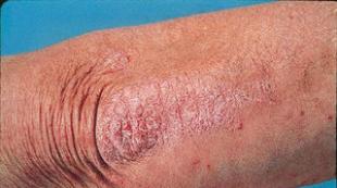
On the territory of the EAP branch of the State Unitary Enterprise TEK SPb, a section of the PPU heating network pipeline of nominal diameter Du57 was installed using shaped products, a bellows compensator and an end element (Fig. 1, photo 1).
To model defective sections of the heating network, unsealed joints with tin gutters were left on the model (photo 2). The remaining joints are made by pouring foaming components using heat-shrinkable sleeves.
When installing the UEC system in accordance with SP 41-105-2002 (NYM type cable), a 10-meter cable from the reflectometer connection point to the pipeline and a 5-meter cable at the intermediate end element were used.
Installation of the UEC system according to EMS (ABB) technology (using a connecting coaxial cable and matching transformers of the “connecting wire - signal conductor” line) was carried out using a 10-meter coaxial cable from the reflectometer connection point to the pipeline (photo 3).
To reduce losses in the interrogation line, the reflectometer was connected to the cable using coaxial fittings.
The measurements were carried out with reflectometers REIS-105 and mTDR-007 (taking reflectograms) when simulating the most likely types of defects in the heating network: break, short circuit of the conductor to the pipe, single and double wetting of the insulation (in different places).
As part of this experiment, the possibilities of combined use various cables when installing the interrogation line of signal conductors SODK (presence of a pass-through terminal) in the following sequence: coaxial cable - conductor ODK - NYM cable - conductor ODK with a break in the conductors at the end of the interrogation line.
As a result of the tests and measurements, the following conclusions can be drawn.
1. The attenuation of the probing pulse in a NYM type cable (Fig. 2b) is several times higher than in a coaxial cable (Fig. 2a). This reduces the length of the surveyed area, limiting effective application locator in areas from camera to camera (150-200 m).
2. Due to the large power losses of the probing pulse, when it passes through the NYM cable, it is necessary to increase its energy by increasing the pulse duration, which leads to a decrease in the accuracy of determining the distance to the location of the pipeline defect.
3. The absence of matching elements at the “cable-pipe” and “pipe-cable” transitions leads to a change in the shape of the reflected pulses, smoothes out their fronts and reduces the accuracy of determining the location of the insulation defect (Fig. 3).

Russian pipes in PPU insulation have different wave properties and parameters from imported ones. The complex electrical resistance (impedance) of pipes and fittings in practice varies from 267 to 361 Ohms (ABB pipes have an impedance of 211 Ohms), therefore the use of foreign matching devices on our pipes is impossible (RMS LLC has developed matching devices for PU foam pipes manufactured according to Russian standards, there is positive experience of their practical application on real objects).

This point of conclusions deserves special attention in view of its importance for the operation of the SODS.
The spread of impedance for different pipe elements leads to variations in the so-called shortening coefficient for these pipe elements. As is known, measurements are carried out at one shortening coefficient common to the entire pipeline. Thus, having sections along the pipeline with different shortening coefficients, we will get a discrepancy between the measured electrical parameters and the real physical parameters of the pipelines, and the discrepancy will be greater the longer the pipeline and the more fittings on it (in practice, the discrepancy reaches up to 5 m per 100 -meter section of the pipeline).
For high-quality execution of the as-built documentation for the SDSK, it is necessary to monitor not only the insulation resistance and ohmic resistance of the conductor loop, but also measure the shortening coefficient of each mounted pipe element using a reflectometer, recording the measurement results on the as-built diagram of the pipeline. Otherwise, errors when searching for broken conductors and dampening of insulation will lead to an increase in the cost of repair work due to a significant increase in the volume of excavation and restoration work.

The lack of impedance standardization allows unscrupulous manufacturers to use varnished copper winding wire as UDC conductors when producing PU-insulated pipes. This allows you to obtain excellent electrical characteristics during installation and a “perpetually serviceable” pipeline, regardless of any moisture insulation. The UEC system, in this case, is a useless, fake application.
Since impedance depends on dielectric constant environment and the distance from the pipe to the conductor, then the use of non-standard pipe production methods leads, as a rule, to an increase in impedance and, as a consequence, the shortening coefficient of the pipe element. Impedance standardization would make it difficult for low-quality pipes to enter the market.

5. The use of NYM cables as a communication line between the locator and the PPU pipeline with SODK, as well as as connectors between different areas pipelines, completely eliminates the use of stationary specialized fault locators (Fig. 4) and does not allow considering the heating network as an object of automation and dispatch, leaving significant costs for linemen and maintenance personnel (Table 1).
6. Application on one controlled section of the pipeline various types connection cables are ineffective.
The most effective are UEC systems based on the use of coaxial cables with matching devices. Such UEC systems are fully compatible with monitoring devices for PPU pipe conductors (the use of which is prescribed by SP 41-105-2002) and can significantly increase the efficiency of their use.
The use of coaxial communication cables between pipelines will open up the possibility of using specialized stationary fault locators for heating networks. Which, in turn, will allow:
Merge later local systems UEC into a single network with the necessary hierarchy;
Display the status of local SODS at the central control center indicating the specific location of the network defect (example of implementation similar system The experience of the State Unitary Enterprise "TEK SPb" can serve);
Promptly take measures to eliminate defects in initial stage their occurrence;
Reduce operating costs of UEC systems (Table 1);
Save significant funds on emergency repairs of heating networks (Table 2);
Increase network reliability by reducing emergency outages;
Receive objective information about defects and the state of thermal and waterproofing on the heating network by eliminating the influence of the subjective human factor in this kind of questions.

In conclusion, it should be noted that the UEC pipeline system only at first glance seems simple and even primitive in installation. Majority construction organizations they trust the installation of ODS to ordinary electricians, who install ODS like ordinary lighting networks or underground cable installations. As a result, instead of an effective means of control, organizations operating heat networks receive a useless application to the heat network.
It should also be noted that properly installed UEC systems make it possible to realize all the advantages of pipelines with polyurethane foam insulation, in particular, to automate as much as possible the search for places of moisture and damage to pipeline insulation, and to increase the accuracy of identifying these places. Pipelines with other types of insulation (APb, PPM, etc.) in principle do not have similar advantages.
Installation of ODS should be carried out by professional organizations that understand all the subtleties and nuances in detecting defects using reflectometers, having necessary equipment, practical experience construction and adjustment of systems. Only professionals are able to create effectively working systems - SODK is no exception to this rule.
Literature
1. SP 41-105-2002. Design and construction of ductless heating networks made of steel pipes with industrial thermal insulation made of polyurethane foam in a polyethylene shell.
2. SNiP 41-02-2003. Heat networks.
3. Slepchenok V.S. Experience in operating a municipal heat and power plant. Uch. manual - St. Petersburg, PEIpk, 2003, 185 p.