Equation of state of an ideal gas. Thermal engineering studies of open hearth furnaces
The partial pressure of each gas included in the mixture is the pressure that would be created by the same mass of a given gas if it occupied the entire volume of the mixture at the same temperature.
In nature and technology, we very often deal not only with one pure gas, but with a mixture of several gases. For example, air is a mixture of nitrogen, oxygen, argon, carbon dioxide and other gases. What does the pressure of a gas mixture depend on?
In 1801, John Dalton established that the pressure of a mixture of several gases is equal to the sum of the partial pressures of all gases making up the mixture.
This law was called law of partial pressures of gases
Dalton's law The partial pressure of each gas included in a mixture is the pressure that would be created by the same mass of a given gas if it occupied the entire volume of the mixture at the same temperature.
Dalton's law states that the pressure of a mixture of (ideal) gases is the sum of the partial pressures of the components of the mixture (the partial pressure of a component is the pressure that a component would exert if it alone occupied the entire space occupied by the mixture). This law indicates that each component is not affected by the presence of other components and the properties of the components in the mixture do not change.
Dalton's two laws
Law 1 The pressure of a mixture of gases is equal to the sum of their partial pressures. It follows from this that the partial pressure of a component of a gas mixture is equal to the product of the pressure of the mixture and the mole fraction of this component.
Law 2 The solubility of a component of a gas mixture in a given liquid at a constant temperature is proportional to the partial pressure of this component and does not depend on the pressure of the mixture and the nature of other components.
The laws were formulated by J. Dalton resp. in 1801 and 1803.
Dalton's Law Equation
As already noted, the individual components of a gas mixture are considered independent. Therefore, each component creates pressure:
\[ p = p_i k T \quad \left(1\right), \]
and the total pressure is equal to the sum of the pressures of the components:
\[ p = p_(01) k T + p_(02) k T + \cdots + p_(i) k T = p_(01) + p_(02) + \cdots + p_(i) \quad \left( 2\right),\]
where \(p_i\) is the partial pressure of the i gas component. This equation is Dalton's law.
At high concentrations and high pressures, Dalton's law is not fulfilled exactly. Since there is interaction between the components of the mixture. The components are no longer independent. Dalton explained his law using the atomistic hypothesis.
Let there be i component in a mixture of gases, then the Mendeleev-Cliperon equation will have the form:
\[ ((p)_1+p_2+\dots +p_i)V=(\frac(m_1)((\mu )_1)+\frac(m_2)((\mu )_2)+\dots +\frac(m_i )((\mu )_i))RT\ \quad \left(3\right), \]
where \(m_i\) are the masses of the components of the gas mixture, \((\mu )_i\) are the molar masses of the components of the gas mixture.
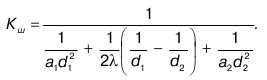
If you enter \(\left\langle \mu \right\rangle \) such that:
\[ \frac(1)(\left\langle \mu \right\rangle )=\frac(1)(m)\left[\frac(m_1)((\mu )_1)+\frac(m_2)( (\mu )_2)+\dots +\frac(m_i)((\mu )_i)\right] \quad \left(4\right), \]
then we write equation (3) in the form:
\[ pV=\frac(m)(\left\langle \mu \right\rangle )RT \quad \left(5\right). \]
Dalton's law can be written as:
\[ p=\sum\limits^N_(i=1)(p_i)=\frac(RT)(V)\sum\limits^N_(i=1)((\nu )_i)\ \quad \left (6\right). \]
\[ p_i=x_ip\ \quad \left(7\right), \]
Where \(x_i-molar\ concentration\ of the i-th\) gas in the mixture, while:
\[ x_i=\frac((\nu )_i)(\sum\limits^N_(i=1)(n_i))\ \quad \left(8\right), \]
where \((\nu )_i \) is the number of moles of \(i-th \) gas in the mixture.
Javascript is disabled in your browser.To perform calculations, you must enable ActiveX controls!
This law shows the property of additivity of partial volume.
v cm =Sv i
v i /v cm =n i /N=y i
v i =y i ×v c m
Used in calculations of gas fields.
33. Equation of state of ideal gases, supercompressibility coefficient
SUPERCOMPRESSIBILITY COEFFICIENT OF NATURAL GASES
Gases - real and ideal.
Ideal gases are when the interaction of molecules with each other is neglected.
P – absolute pressure (Pa), V – volume (m 3), G – mass of the substance (kg), T – temperature (K), R – universal gas constant (kJ/K×kg).
(for an ideal gas).
z is the degree of deviation of a real gas from an ideal one, or the compressibility coefficient of a real gas.
34. Van der Wals equation and its physical meaning
The property of ideal gases is that: P×V/(G×R×T)=1=z.
The new coefficient z we introduced, which for ideal gases is equal to 1, but for real gases is different from it, is called supercompressibility coefficient.
z is the coefficient by which the properties of ideal gases are applied to real ones. It characterizes the degree of deviation of an ideal gas from a real one.
Various attempts have been made to improve the description:
1) Van der Waals equation:
(P+a/v 2)(v-v)=R×T,
where v is the specific volume; c – correction for the volume of molecules; a/v 2 =const – molecular adhesion constant.
The value a/v 2 expresses internal pressure, which is like the resultant force of attraction of all molecules in volume v.
At pressures up to 100 MPa and temperatures T=150°C, it is necessary to determine the most accurate description of the dependencies. In considering this issue, science has taken two directions:
1. introduction of the supercompressibility coefficient z;
2. adding additional constants to the equation of state.
2) Any experimental dependence can be described using a polynomial, so the path of increasing the number of constants was chosen. The most common were equations with five Beatty-Bridgeman constants and eight Benedict-Webb-Rubin constants. All constant quantities are determined by the least squares method.
35. Reduced and critical parameters of gases and their mixtures
I. Introduction of z into the equation of state. Based on experiments, it became clear: if our given parameters P pr, T pr are the same and are in the corresponding states, then such thermodynamic properties as the supercompressibility coefficient are the same for different gases. Those. z=f(P pr, T pr).
The given parameters ideal components - dimensionless quantities showing how many times the actual parameters of the state of gases are greater than the critical ones. The parameters are understood as: P abs, T, V and z.
T pr = T/T cr; R pr = R/R cr; z pr =z/z cr.
The given parameters are calculated based on the critical parameters, from here we will consider the issue of determining the critical parameters.
 Р кр =Sу i ×Р крi; T cr =Sу i ×T cri; z cr =Sу i ×z cri
The dependencies of the given parameters are as follows: z T pr
36 Dependence of the supercompressibility coefficient of natural gas on the reduced pressure and temperature
The given parameter is a dimensionless quantity that shows how many times the parameters P,V,r are greater or less than the critical ones.
 Real gases
– a mixture of hydrocarbon and non-hydrocarbon components. The molecules of argon, xenon, krypton and methane have a spherical configuration. The molecules of gases such as propane and butane are non-spherical, therefore, to take into account the shape of the molecules, the parameter was introduced - acentric factor
(w). It shows that if the molecule is spherical, then the forces that act on it are spherical, which indicates the symmetry of the forces. If the molecules are not spherical, then an asymmetry of the acting forces arises.
Real gases
– a mixture of hydrocarbon and non-hydrocarbon components. The molecules of argon, xenon, krypton and methane have a spherical configuration. The molecules of gases such as propane and butane are non-spherical, therefore, to take into account the shape of the molecules, the parameter was introduced - acentric factor
(w). It shows that if the molecule is spherical, then the forces that act on it are spherical, which indicates the symmetry of the forces. If the molecules are not spherical, then an asymmetry of the acting forces arises.
z=z(P pr, T pr, w)
z cm =z 0 (P pr, T pr)+z 1 (P pr, T pr)×w cm,
where z 0 is the supercompressibility coefficient of a simple gas. For a simple gas, the molecules are spherical and w=0.
z 1 – correction to the supercompressibility coefficient of a complex gas, which depends on P pr, T pr and w¹0.
w cm is the acentric factor of the entire mixture, characterized by certain concentrations:
w cm =Sу i ×w i
From this we can see that the acentric factor of the mixture depends on the acentric factor of each component.
y i is the molar concentration of the component.
37 Density of natural gas and stable hydrocarbon condensate
For natural gas:
r P, t =r P0, t0 ×(P×z 0 ×T 0)/(P 0 ×z×T)
For stable condensate:
r(C 5+)=1.003×M k /(M k +44.29)[kg/cm 3 ]
From the refractive index determined experimentally, one can calculate:
1gM to =1.939+0.0019×t to +1g(2.15 - n D),
where tk is the boiling point of the condensate; n D – refractive index.
These coefficients are empirical in nature.
But the density of stable condensate can be calculated using another formula, namely:
r к =Sх i ×М i /Sх i ×n i /r i ,
where x i is the mole fraction of the i-th component;
r i – density of the i-th component;
M i – molecular weight.
________________________
Gas density. The greater the proportion of components with high molecular weight in a gas, the greater the molecular weight of the gas, which is linearly related to the density of the gas:
ρcm = Msm/22.41
Typically ρ is in the range of 0.73 - 1 kg/m3. the density of individual components of hydrocarbon gases (and hydrogen sulfide), with the exception of methane, is greater than 1.
To characterize the gas density, its ratio to the air density under the same conditions is also used (air density under normal conditions is 1.293 kg/m3).
where is the relative gas density; ρcm, ρв – density of gas and air, respectively. The relationship between the density of a gas and its molecular weight, pressure and temperature is determined by the law of state of gases, which can be represented as:
38 Viscosity of gas and gas mixtures
Viscosity of gases. The viscosity of a gas depends on its composition, pressure and temperature. The viscosity of gases is due to the exchange of momentum between layers of gas moving at different speeds relative to each other. This exchange occurs due to the transition of molecules from one layer to another during their chaotic movement. Since large molecules have a shorter free path (the probability of their collision with each other is relatively high), the amount of motion transferred by them from layer to layer is less than that of small molecules. Therefore, the viscosity of gases usually decreases with increasing molecular weight.
 With increasing temperature, the speed of movement of molecules increases and, accordingly, the amount of movement transferred by them from layer to layer, therefore, at low pressures, the viscosity of the gas increases with increasing temperature. At high pressures, when the distances between molecules are small, the transfer of momentum from layer to layer changes somewhat. It occurs mainly as in liquids due to the temporary association of molecules at the boundaries of layers moving at different speeds. The probability of such unification decreases with increasing temperature. Therefore, at high pressures, the viscosity of gases decreases with increasing temperature.
With increasing pressure, the viscosity of gases increases: at low pressures it increases slightly and more intensely at high pressures.
The viscosity of a gas is determined experimentally by measuring its flow rate in capillaries, the speed at which a ball falls in the gas, the damping of rotational oscillations of the disk, and other methods. The change in viscosity at different pressures and temperatures can be determined by calculation and from graphs depending on the given pressure and temperature.
Gas viscosity at low pressure and temperatures close ideal gas viscosity. This means that we can use the kinematic theory by writing the equation for a rarefied gas:
m=r×v×l/3,
where v is the average speed of movement of molecules; l is the free path length.
According to kinetic theory, viscosity depends on pressure and temperature:
With increasing pressure, the density increases, but l decreases, which results in an increase in the probability of collision, the average speed of movement is constant, and the viscosity in the initial period is almost constant (Dр<<).
With increasing temperature, viscosity increases, because The average speed of movement of molecules increases, and the density and mean free path practically do not change.
At the same time, from the definition of viscosity, the forces that prevent the movement of one layer relative to another must change, and, therefore, the change in viscosity is complex.
 m Р max
At low pressures m depends little on the pressure drop. With increasing pressure and increasing temperature, the viscosity of gases (m) decreases.
If the molecular weight of a gas increases, the viscosity will increase accordingly.
The presence of non-hydrocarbon gases and their effect on viscosity is taken into account as follows:
m=у а ×m а +(1 – у а)×m у,
where y is the mole fraction;
m a – viscosity of non-hydrocarbon gas;
m y – viscosity of hydrocarbon gas.
The dependence of m on molecular weight can be graphically depicted:

39. Dependence of gas viscosity on composition and thermobaric conditions
40 Isobaric molar heat capacity of natural gases
Let's consider two main thermodynamic processes: at constant pressure (isobaric) and at constant volume (isochoric).
To calculate the processes occurring in gases, the concepts are used isobaric And isochoric specific heat capacities .
С р =(dQ/dТ) р
С v =(dQ/dТ)v
dQ=di - v×dр,
where i is the enthalpy of an ideal gas.
di=dQ+v×dр=С р ×dТ+(v – Т×(dр/dТ) р)dv
When p=const: dQ=di=С р ×dТ Þ С р =(di/dТ) р
That. C p depends on temperature.
With ri =0.523×(8.36+0.008×t)m i 3/4[kJ/(kmol×K)]
The heat capacity of real gases is determined by the additivity rule, i.e.:
С рсм =Су i ×С рi
Isobaric molar heat capacity depends on pressure and temperature:
C p =C ri (t)+DC p (p,t),
where DСр is the isothermal correction of the heat capacity for pressure and temperature.
 T pr
T pr
The states of hydrocarbon systems are of particular relevance, because are in the region of critical states, where phase transformations take place.
All equations obtained based on experiment are semi-empirical in nature.
41 Dependence of the isobaric molar heat capacity of real gases on pressure and temperature
42 Penta-Robinson equation of state
43 Penta-Robinson equation regarding the supercompressibility coefficient
44 Using the Penta-Robinson equation to describe the deviation of the thermal-physical properties of gases
Solving problems related to gas production, transportation and processing is related to the Peng-Robinson equation (1975):
Р=R×Т/(v–в)=а(Т)/(v×(v+в)+в×(v-в)),
where a(T), b are coefficients determined by critical parameters, and a(T) is a certain function.
v – molecular volume.
z 3 – (1 - B)×z 2 + (A - 3×B 2 - 2×B)×z – (A×B – B 2 – B 3) = 0,
where A=a(T)×P/(R 2 ×T 2),
V=v×P/(R×T)
If the mixture is in a two-phase state, then the larger root corresponds to the vapor phase, and the smaller root corresponds to the liquid phase.
Under critical conditions, z cr =const is a constant value - and z cr =0.307. Then:
a(T cr)=0.45724×R 2 ×T cr 2 /R cr
v(T cr)=0.0778×R×T cr/R cr
If the temperature is different from the critical one, then these coefficients depend on Tcr:
a(T)=a(T cr)×a(T cr,w);
in (T) = in (T cr),
where w is a dimensionless function.
At T=T cr a=1.
The relationship between a and temperature (T) can be written as follows:
a 0.5 =1+m×(1 – T 0.5), m=f(w).
For a mixture, the Peng-Robinson equation looks like this:
a cm (T)=Sу i ×а i;
in cm (T)=Sу i ×в i,
where ai and bi are calculated using the formulas:
a i =0.457×(R 2 ×T cr i 2 /R cr i)×a i ;
in i =0.0778×R×T cr i /R cr i
45 Elasticity of saturated vapors of hydrocarbon systems and their mixtures
46 Henry's Law
Solubility of gases in liquids. At high pressures, the solubility of gases in liquids, including oil, obeys Henry's law. According to this law, the amount of gas Vr dissolving at a given temperature in the volume of liquid Vl is directly proportional to the gas pressure p above the surface of the liquid:
Vg = α∙р∙V (2.8)
where [a]=[m 2 /N] – Henry's coefficient , taking into account the amount of gas dissolving in a unit volume of liquid when the pressure increases by one unit.
a=V g /(V f ×p)
The solubility coefficient shows how much gas dissolves in a unit volume of oil when the pressure increases by one unit. The solubility coefficient of gas in oil is not a constant value. Depending on the composition of oil and gas, temperature and other factors, it varies from 0.4∙10-5 to 5∙10-5 1/Pa.
The solubility of gas in oil is most influenced by the composition of the gas itself. Light gases (nitrogen, methane) are less soluble in oils than gases with a relatively higher molecular weight (ethane, propane, carbon dioxide). In oils containing more light hydrocarbons, the solubility of gases is higher compared to heavy oils. As temperature increases, the solubility of gases in oil decreases.
From Henry's law it follows that the higher the solubility coefficient, the lower the pressure in a given volume of oil the same volume of gas dissolves. Therefore, oils with a high methane content at high reservoir temperatures usually have high saturation pressures, and heavy oils with a low methane content at low reservoir temperatures have low saturation pressures. The amount of dissolved gas is associated with the difference in the physical properties of oil in reservoir conditions and on the surface.
47 Solubility of gases in oil and water
The solubility characteristics of gas in oil are as follows:
 cm 3 /cm 3
The abscissa shows the pressure values, and the ordinate shows the amount of gas dissolved in the oil.
The solubility of gases increases with increasing molecular weight of the gas. Consequently, different gas components have different solubilities, which means that natural gas will dissolve in natural oil in a complex manner.
Solubility depends on the composition and properties of the oil. Moreover, the solubility of gases increases with increasing content of paraffin hydrocarbons, and with a high content of aromatic hydrocarbons.
Slightly soluble gases obey Henry's law better than highly soluble gases.
The solubility of gases in oil is influenced by the nature of the gas to a greater extent than by the composition of the oil, although in compressed gas at high pressures a reversible dissolution of oil components occurs, which can be seen in the flattening of the solubility curves of highly soluble gases.
Solubility coefficient oil gases varies widely and reaches (4-5) × 10 -5 m 3 / (m 3 × Pa).
Hydrocarbon gases become less soluble in oil with increasing temperature.
In addition to the dissolution process, there is a process of gas release from oil. Dissolution is associated with geological conditions, and the process itself took place over a long period. And the process of separation is connected with our activities, and it is already short-term.
contact differential
48 Solubility isotherms of natural gases in oils
The amount of gas released depends on the choice of technology:
Gas has been released and is in contact with oil (gas caps);
Gas was released and we removed it from the oil-gas system (with outlet).
The first of these degassing methods is called contact , or single-stage. Second - differential , or stepwise (multiple).
If the process is differential, then the amount of gas remaining in a dissolved state in the oil is greater than in a contact (single-stage) process. This is due to the transition of methane to the vapor phase.
The amount of gas released from oil is characterized by degassing curves. They are obtained experimentally, and each deposit has its own curve.
 cm 3 /cm 3
Degassing coefficient It is customary to call the amount of gas released from a unit volume of oil when the pressure decreases by one unit.
In a certain pressure range, degassing does not occur.
If the gas degasses, the phase permeability of the oil decreases.
49 Contact and differential degassing of oil
 2 types of degassing curves:
1) contact type - all released gas remains.
2) differential type - gas is removed. Characteristic for laboratory conditions.
For differential Degassing - the amount of gas is greater than with contact.
Degassing curve:
50 Oil degassing coefficient
The degassing coefficient is usually called the amount of gas released when the pressure decreases by one unit.
In addition to oil, there may be a large amount of water in the formation.
51 Solubility of hydrocarbon gases in water
52
53 How do thermobaric conditions affect saturation pressure?
Oil gas saturation pressure – the maximum pressure at which gas begins to be released from oil in an isothermal process, under conditions of thermodynamic equilibrium.
 Among other things, the saturation pressure depends on the temperature and increases with its growth.
If the saturation pressure is approximately equal to the reservoir pressure, and we inject cold water, then the reservoir temperature will decrease, which means that gas can be released due to a decrease in pressure.
Stepanova discovered that with a very small gas release (hundredths of percent), a lubrication effect occurs and the phase permeability of oil increases abnormally.
When we irradiate the rock with ultrasound, gas bubbles begin to be released; control over this process will allow us to regulate the phase permeability. The number of bubbles released depends on the skeleton of the rock and the composition of the formation. From this we can conclude that the saturation pressure varies throughout the formation.
54 Oil compressibility and its characterizing components
Oil has elasticity, which is measured compressibility coefficient (or volumetric elasticity ).
b n =-1/V×(dV/dр)
It is of the order of (0.4¼0.7) GPa -1 (for oils that do not contain dissolved gas). Light oils containing a significant amount of dissolved gas have an increased compressibility coefficient (bn reaches 14 GPa -1).
b n depends on temperature and pressure, and the higher the temperature, the greater the compressibility coefficient.
 |
When oil from a reservoir rises to the surface, its composition changes and its volume changes.
The volumetric coefficient is calculated using the formula:
in = V pl / V money,
where Vpl is the volume of oil in reservoir conditions;
V money is the volume of degassed oil (on the surface).
 The dependence of the volume coefficient on pressure is as follows.
To carry out thermodynamic calculations of systems with gas mixtures or solutions, it is necessary to know their composition. The composition of the mixture can be specified:
In mass fractions, where 
 - molar mass i-th component, kg/mol; M i– relative molecular weight i-th component; n i- quantity i-th substance, mole;
for each phase  ;
;
Mole fractions  , Where
  - amount of mixture substance, mol; for each phase the sum of the mole fractions of the mixture components
  ;
;
Volume fractions, which are equal to mole fractions  , Where
  - volume i the th component of the mixture, which at the temperature and pressure of the gas mixture is called the reduced volume;
  , m 3 /mol – molar volume of the i-th component of the mixture. In accordance with Avagadro's law, the molar volumes of all components of a mixture of gases are equal and
  , Where
  . The sum of the reduced volumes of the components of a gas mixture is equal to the volume of the mixture (Amag’s law), i.e.
  .
.
The composition of a mixture of ideal gases can also be specified by partial pressures r i, mass concentrations  and molar concentrations
  .
.
When specifying the composition of solutions, mass and molar concentrations are used.
Partial pressure r i - this is pressure i th component of the gas mixture, provided that it occupies the entire volume intended for the mixture at the temperature of the mixture.
3.2. Relations for mixtures of ideal gases. Dalton's law
The average molar mass of a mixture of gases is determined by the expression  , kg/mol, where
  - mass of the mixture;
  - the amount of substance in the mixture. Then
 .
.
Specific gas constant of a gas mixture
 , J/(kgK),
Where  J/(molK) – molar gas constant;
  - molar mass of the mixture.
Dalton's Law:
 , Pa,
, Pa,
those. the sum of the partial pressures of the individual gases included in the mixture is equal to the total pressure of the mixture. Thus, each gas in the vessel occupies the entire volume at the temperature of the mixture, being under its own partial pressure.
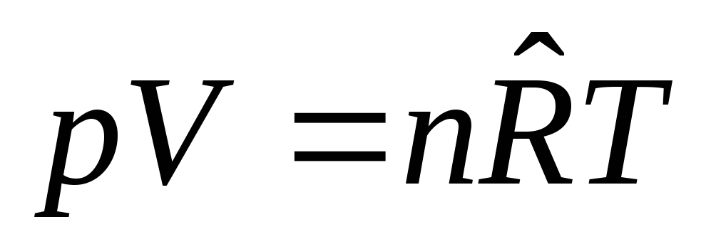
The equation of state for a mixture of ideal gases has the form:
 .
.
For partial pressure and for reduced volume i- th component of the mixture, the equations of state have the form:

Then, dividing these equations term by term, the first by the second, we have
 .
.
Dividing the equation  to the equation
  term by term, we get:
 .
.
Chapter 4. Heat capacity
4.1. Types of heat capacity
Heat capacity is the property of bodies to absorb and release heat when the temperature changes by one degree in various thermodynamic processes. A distinction is made between total average and total true heat capacity.
The total average heat capacity of a thermodynamic process (TP) is the heat capacity of a body with mass m, kg for the final segment of the TP:
 ,[J/K].
The total true heat capacity of a TP is the heat capacity of a body with a mass m, kg at each given moment TP:
 , [J/K].
Consider an arbitrary TP 1-2 in coordinates  , Where Q– heat input in [J]; t
– temperature in [ 0 C]. Then
, Where Q– heat input in [J]; t
– temperature in [ 0 C]. Then  ,
, .
.

If the vehicle is a homogeneous working fluid, then the relative heat capacities are used in the calculations:
Specific heat capacity – heat capacity per 1 kg of substance c=C/m, J/kgK;
Molar heat capacity – heat capacity per 1 mole of a substance  , J/molK;
Volumetric heat capacity – heat capacity per 1m3 of substance  , J/m 3 K.
Heat capacity is a function of the process and depends on the type of working fluid, the nature of the process and state parameters. Thus, the heat capacity in a process with constant pressure is called isobaric heat capacity:
 ,
,
Where H, J – enthalpy.
The heat capacity in a process with constant volume is called isochoric heat capacity:
 ,
,
Where U, J – internal energy.
The heat capacity of an ideal gas does not depend on temperature and pressure and depends only on the number of degrees of freedom of movement of molecules and, in accordance with the law of equal distribution of energy among the degrees of freedom of movement of molecules, the heat capacity is:  , Where
  - rotational degrees of freedom equal to zero for a monatomic gas
  , for a diatomic gas -
  =2 and for triatomic gases
  =3;
=3; J/molK – molar gas constant. Heat capacity
  determined by Mayer's equation:
 .
.
For monatomic gas  And
And  , for diatomic gas
  And
And  , for three or more atomic gases
  And
And  .
.
The heat capacity of real gases depends on pressure and temperature. In a number of cases, we can neglect the effect of pressure on the heat capacity and assume that the heat capacity of real gases depends only on temperature: C= f(t). This dependence is determined experimentally.
The empirical dependence of the specific true heat capacity on temperature can be represented as a polynomial:
Where  at temperature t=0 0 C. For diatomic gases, we can limit ourselves to two terms:
  , or
, or  , Where
  .
.
For the final section of process 1-2, the amount of heat is equal to:
Then the average heat capacity in this section of the process will be equal to:
 , J/kgK.
In the region of low temperatures at T<100К прекращается вращательное движение молекул и колебательное движение атомов, а при температуреT→0K the translational motion of molecules also stops, i.e. at T=0K WITH r = C v=0 and the thermal movement of molecules stops (experimental data from Nernst et al., 1906-1912). At temperature T→0K the properties of substances cease to depend on temperature, as is illustrated in the above graph of the dependence of heat capacity on absolute temperature.

Submitting your good work to the knowledge base is easy. Use the form below
Students, graduate students, young scientists who use the knowledge base in their studies and work will be very grateful to you.
Posted on http://www.allbest.ru/
Introduction
Thermal engineering is a science that studies methods of obtaining, converting, transferring and using heat, as well as the principles of operation and design features of heat engines, apparatus and devices. Heat is used in all areas of human activity.
To establish the most rational ways of using it, analyze the efficiency of working processes of thermal installations and create new, most advanced types of thermal units, it is necessary to develop the theoretical foundations of heating engineering. There are two fundamentally different directions for the use of heat - energy and technological.
When used as energy, heat is converted into mechanical work, with the help of which electrical energy is created in generators, convenient for transmission over a distance. Heat is obtained by burning fuel in boiler plants or directly in internal combustion engines.
In technological processes, heat is used to purposefully change the properties of various bodies (melting, solidifying, changing the structure, mechanical, physical, chemical properties). The amount of energy resources produced and consumed is enormous.
Thermal engineering is a general technical discipline in the training of specialists in technical specialties and consists of three interrelated subjects: technical thermodynamics, the foundations of heat transfer theory, in which the laws of transformation and properties of thermal energy and the processes of heat propagation are studied.
The objective of the thermal engineering course is to prepare a chemical engineer-technologist who has the skills to competently manage the design and operation of modern chemical production, which is a set of technological and thermal processes and corresponding technological and thermal power equipment. This training will contribute to the successful implementation of the above tasks by graduates of chemical engineering universities. The importance of such preparation will grow as nuclear, thermonuclear and renewable types of energy are included in the range of practically significant and effective ones, because, as the well-known expression goes, no type of energy is as expensive as its lack.
gas partial gas turbine convective
Theoretical question No. 1
The concept of a gas mixture. Partial pressure. Dalton's law. Partial volume. Amag's Law. Methods for specifying gas mixtures. Fire hazard of flammable mixtures with air
A gas mixture is a mixture of several ideal gases that do not enter into any chemical reactions with each other. Examples of a gas mixture include: atmospheric air, which consists of a mixture of predominantly nitrogen and oxygen; natural gas; exhaust gas of internal combustion engines (ICE), which contains CO 2, CO, N 2, NO 2, O 2 and other gases, moist air (water vapor) in drying units, etc.
The main principle that determines the properties of a gas mixture is the principle of independence of the action of gases in the mixture, that is, each gas in the mixture acts independently of other gases, does not change its properties and obeys all gas laws. In addition, each gas occupies the entire volume of the mixture and all gases in the mixture have the same temperature, and the properties of the mixture of gases are the sum of the properties of all its components.
It follows from this that gas mixtures obey the same laws and equations as homogeneous ideal gases. The basic law that determines the behavior of a gas mixture is Dalton’s law: the total pressure of a gas mixture of ideal gases is equal to the sum of the partial pressures of all its components:
R cm= p 1 + p 2 + … + r n =
where P cm is the pressure of the gas mixture; P 1, P 2, P n - partial pressures of the mixture components.
Each component of the mixture, occupying the entire volume of the mixture, is under its own partial pressure. But if this component is placed under pressure P cm at the same temperature of the mixture T cm, then it will occupy a volume smaller (V i) than the volume of the mixture V cm). This volume Vi is called reduced or partial.
Partial pressure is calculated using the equation of state of a given component:
Hence, .
To compare gases included in a mixture by volume, the concept of partial volume is introduced.
The partial (reduced) volume of a given component is the conditional volume that a given component would have if it alone were at the temperature and pressure of the mixture. The relationship between the volume of a gas mixture and the partial volumes of individual gases in the mixture reflects Amag’s law (additivity law): the total volume of a gas mixture is equal to the sum of the partial volumes of its components:
V cm= V 1 + V 2 +...+ V n = .
To calculate the partial volume, we write two equations of state for any gas included in the mixture:
the first is when a gas having a partial pressure R 1 , occupies the entire volume of the mixture V cm has the temperature of the mixture T cm:
R 1 V cm=m 1 R 1 ·T cm;
the second - when the gas has a reduced volume Vi at pressure P cm and mixture temperature T cm:
R cmV 1 =m 1 R 1 ·T cm.
Dividing the first equation by the second, we obtain the equations of state of the component
where P cm and V cm are the pressure and volume of the mixture; P i and Vi are the pressure and volume of the i component.
From here we express the partial volume of the component:
The properties of a gas mixture depend on its composition, which can be specified by mass, volume and mole fractions.
Mass fraction component of a mixture g i is a value equal to the ratio of the mass of the component to the mass of the entire mixture:
where m i is the mass of this component; m cm is the mass of the entire mixture containing n components.
Since the mass of the mixture m is equal to the sum of the masses of all components:
then the sum of the mass fractions is equal to:
Knowing the mass fractions of individual gases included in the mixture, it is possible to determine their partial pressures
hence
Mass fractions are often specified as percentages. For example, for dry air: g(N 2) = 77%; g(O 2) = 23%.
Volume fraction mixture component r i is a value equal to the ratio of the partial volume of the component to the volume of the mixture:
Where V i- partial volume of a given component; V cm- volume of the entire mixture.
Since the volume of the mixture is equal to the sum of the partial volumes of the components, the sum of the volume fractions is equal to: .
Volume fractions are specified as percentages. For example, for air: r(N 2) = 79%; r(O 2) = 21%.
Mole fraction component of a mixture x i is a value equal to the ratio of the number of moles of this component to the total number of moles of the mixture:
Since the total number of moles of the mixture is equal to the sum of the numbers of moles of each component, it is obvious that:
In accordance with Avogadro's law, the volumes of a mole of any gas at the same pressure and temperature, in particular at the temperature and pressure of the mixture, are the same in the ideal gas state. Therefore, the reduced volume of any component can be calculated as the product of the volume of a mole V m by the number of moles of this component, i.e. V i = V mN, and the volume of the mixture is according to the formula V = V mN.
therefore, specifying the gases included in the mixture in mole fractions is equal to specifying their volume fractions.
The relationship between mass and mole fraction can be found from the equation:
As a result, we have the following relations:
In the resulting equations M CM- average (apparent) molecular weight of a given gas mixture, i.e. molecular weight of such a conditional homogeneous gas, which in its properties is similar to a given gas mixture.
Based on this, the value M CM determined by the composition of the mixture as follows:
Since the ratio:
Adding dependencies for magnitude g i for all components of the gas mixture, we have:
After transformations we get:
The equation of state for a gas mixture can be adopted for the following reasons. From the principle of independence it follows that if each gas in a mixture, independently of the others, obeys the equation of state, then the entire mixture can be considered as one homogeneous gas with its own special properties, which also obeys the equation of state, i.e.
Where R C.M.- average apparent gas constant of the mixture, determined on the basis of the average molecular weight of the mixture:
Magnitude R C.M. can also be found from the composition of the mixture after substituting dependencies for M CM:
Summing over all components, we get:
The sum on the left side of the equation is equal to the volume of the mixture. Dividing both sides of the equation by the mass of the mixture m we get
The sum on the right side of the equation represents the gas constant of the mixture:
Some gases and vapors in certain mixtures with air are explosive. The fire hazard of gas mixtures is determined by the concentration of flammable gases, vapors or dusts in the mixture. At the lower flammable concentration limit (LCFL), there is a small amount of fuel and excess air in the mixture. As the concentration of fuel increases, a lack of air appears in the mixture, which leads to loss of ignition ability.
An explosion of a mixture can occur only at certain ratios of flammable gases included in the mixture with air or oxygen, characterized by lower and upper explosive limits. When choosing the composition of the mixture, the explosion limits are taken into account. For example, a methane-air mixture is explosive when it contains 5.3-14.9% CH4, and an ammonia-air mixture is explosive when it contains 14.0-27% NH3. Thus, the gas mixture used in production, containing 12-13% CH 4 and 11-12% MN 3, is explosion-proof in air. However, such an initial mixture is close to the explosion limits, and to prevent a possible violation of the composition, automatic regulation of the gas ratio is provided. For complete safety, nitrogen is added to the initial mixture.
Theoretical question No. 2
Gas turbine cycles
Gas turbine units (GTU) are thermal power devices in which the working fluid is gaseous products of fuel combustion (or other gases heated in one way or another), and the working engine is a gas turbine. Gas turbines are classified as internal combustion engines. They differ from piston internal combustion engines in that useful work is performed in them due to the kinetic energy of gas moving at high speed.
Gas turbine units have a number of technical and economic advantages compared to piston engines, namely:
Lighter weight and small installation dimensions with high power;
Absence of a crank-rod mechanism;
Uniformity of stroke and the possibility of direct connection with consumers of work - electric generators, centrifugal compressors, etc.;
Ease of maintenance;
Implementation of a cycle with full expansion and thus with high thermal efficiency;
Possibility of using cheap types of fuel (kerosene).
These advantages of gas turbines have contributed to their spread in many areas of technology.
The design of the first gas turbine was developed by mechanical engineer of the Russian fleet P.D. Kuzminsky in 1897. It was intended for a small boat. A distinctive feature of this turbine was its operation with water vapor, which was injected into the combustion chamber to lower the temperature of the gases in front of the turbine.
The widespread use of gas turbine units became possible only after solving two main problems: the creation of a gas compressor with high efficiency (turbocompressor) and the production of new heat-resistant metal alloys capable of long-term operation at temperatures of 650 - 750 ? C and higher.
The operation of gas turbine plants is based on ideal cycles consisting of the simplest thermodynamic processes. The thermodynamic study of these cycles is based on assumptions similar to internal combustion engine cycles, namely: the cycles are reversible, heat is supplied without changing the chemical composition of the working fluid of the cycle, heat removal is assumed to be reversible, there are no hydraulic and thermal losses, the working fluid is an ideal gas with a constant heat capacity. Unlike piston internal combustion engines, where the processes of compression, heat supply and expansion are carried out in the same cylinder, in gas turbine units these processes occur in various elements of the installation, into which the flow of the working fluid sequentially enters. Gas turbines can operate with fuel combustion at constant pressure and constant volume. The corresponding ideal cycles are divided into cycles:
With heat input at constant pressure ( P = const) -- Brayton cycle;
With heat input at constant volume ( v = const) -- Humphrey cycle;.
Cycle with heat recovery.
The cycle with heat supply at constant pressure has received the greatest practical application.
p= const(Brighton cycle)
The schematic diagram of a gas turbine unit, in which fuel combustion occurs at constant pressure, is shown in Fig. 1, and the reversible cycle carried out in it is presented in the pv and Ts diagrams in Fig. 1.1. In this installation, atmospheric air from the environment, having a pressure p 1 and a temperature T 1, enters the input of the compressor (1), rotating on the same shaft as the gas turbine (4). In a compressor, air is compressed adiabatically ( 1-2 ) to a pressure p 2 at which it is supplied to the combustion chamber (3), where gaseous or liquid fuel enters. Here, at constant pressure, fuel combustion occurs at p=idem (2-3 ), as a result of which the temperature of the resulting gaseous combustion products rises to the value T3. At this temperature and pressure p 3 = p 2 the gas enters the turbine (4), where with adiabatic expansion ( 3-4 ) up to atmospheric pressure p 1 performs work, one part of which is spent on driving the compressor, and the other on driving the generator that generates electricity. From the turbine (4), gas at pressure p 4 = p 1 is released into the surrounding atmosphere ( 4-1 ), and new clean air is taken into the compressor from the atmosphere.
The following are accepted as the defining parameters of the ideal cycle:
Air pressure increase ratio or (compression ratio) ;
Degree of pre-expansion.
The main thermodynamic indicator of the efficiency of a cycle is its thermal efficiency
and the amount of heat removed - according to the formula
Then, the thermal efficiency of the cycle
It is usually expressed as a function of the degree of pressure increase y. For adiabatic 1 - 2 we have:
For isobar 2 - 3
For adiabatic 3 - 4
Substituting the obtained temperatures T 2, T 3 and T 4 into the equation of thermal efficiency, we obtain
It follows from the formula that the thermal efficiency of a gas turbine unit with heat supply at constant pressure depends on the degree of pressure increase y and the adiabatic index k, increasing with increasing these values.
Subject to dependency
Consequently, for the same working fluid, an increase in the degree
compression always leads to an increase in efficiency.
Cycle work:
Despite the fact that an increase in the degree of increase in air pressure has a beneficial effect on the efficiency of a gas turbine unit, an increase in this value leads to an increase in the temperature of the gases in front of the turbine blades. The values of this temperature are limited by the heat resistance of the alloys from which the blades are made. Currently, the maximum permissible gas temperature in front of the turbine is 800 - 1000 ° C and a further increase in temperature can only be achieved with the use of new heat-resistant materials and the introduction of turbine designs with cooled blades.
Scheme and cycle of a gas turbine unit with heat supply atV= const (Humphrey cycle)
In a gas turbine unit operating in a cycle with heat supply at a constant volume (V=const), the fuel combustion process occurs with closed intake and exhaust valves installed in the combustion chamber. Compressor 1, driven by turbine 6, supplies compressed air to combustion chamber 4 through a controlled valve 7. The second valve 5 is located at the end of the combustion chamber and is designed to release combustion products to the turbine. Fuel is supplied to the combustion chamber by pump 2 located on the turbine shaft through a nozzle. Fuel supply should be carried out periodically by fuel valve 3.
As the pressure increases, valve 5 opens and combustion products enter the nozzle apparatus and onto the turbine blades 6. When passing through the turbine blades, the gas does work and is released into the environment.
The cycle of this installation consists of adiabatic compression in the compressor ( a-c); heat supply at v= const(c-z); adiabatic expansion of gas in a turbine ( z-e); isobaric transfer of heat by gas to the surrounding air ( e-a). The thermodynamic cycle in pv and Ts coordinates is presented in Figure 2.1. The main parameters of the cycle are:
The degree of pressure increase in the compressor;
The degree of isochoric pressure increase.
The efficiency of a gas turbine turbine cycle with heat supply at a constant volume is determined as:
The gas parameters at characteristic points of the cycle are determined through the initial temperature Ta from the relations:
Substituting these expressions for temperatures into the thermal efficiency formula, we obtain:
Thus, the efficiency value in a gas turbine unit with heat input at a constant volume depends on the degree of pressure increase in the compressor and on the degree of pressure increase in the combustion chamber, which depends on the amount of heat input ( q 1 ) in an isochoric process.
Specific work per cycle is determined:
Comparisons between cycles with heat input at p=const And v= const apparently that at the same degree of pressure increase and the same amount of heat removed, a cycle with heat supply at a constant volume is more profitable than a cycle with heat supply at a constant pressure. This is due to the greater degree of expansion in the cycle v = const, and consequently, high thermal efficiency values. Despite this advantage, the cycle with heat supply at a constant volume has not found wide application in practice due to the complexity of the combustion chamber design and the deterioration of the turbine in a pulsating gas flow, although work to improve this cycle continues.
Due to the complex design of the combustion chamber, the gas turbine cycle with isochoric heat supply is used extremely rarely, even though it has increased efficiency compared to the Brayton cycle.
GTU cycle with heat recovery
One of the measures to increase the thermal efficiency of gas turbine plants is the use of heat recovery. Heat recovery involves using the heat from exhaust gases to preheat the air entering the combustion chamber. Heat regeneration is possible provided that T 4 >T 2. To do this, an additional device is introduced into the installation circuit - a heat exchanger.
The diagram of a gas turbine installation with combustion at P = const with heat recovery is shown in Figure 3. The difference between a gas turbine installation with heat recovery and an installation without regeneration is that compressed air does not enter from compressor 1 immediately into combustion chamber 4, but first passes through the air regenerator - heat exchanger 3, in which it is heated by the heat of the exhaust gases. Accordingly, the gases leaving the turbine, before escaping into the atmosphere, pass through an air regenerator, where they are cooled, heating the compressed air. Thus, a certain part of the heat that was previously carried away by the exhaust gases into the atmosphere is now usefully used.
The cycle of a gas turbine plant with regeneration and isobaric heat supply in P,v - and T,s - diagrams is shown in Figure 1.
Rice. 1 Thermal diagram of a gas turbine unit with heat recovery
The cycle under consideration consists of an adiabatic process of air compression in the compressor 1 - 2, a process 2 - 5, which is an isobaric heating of air in the regenerator, an isobaric process 5 - 3, corresponding to the supply of heat in the combustion chamber due to fuel combustion, a process of adiabatic expansion of gases 3 - 4 in the turbine, isobaric cooling of the exhaust gases in the regenerator 4 - 1.
The amount of heat supplied to the working fluid in an isobaric process
and what is withdrawn in an isobaric process
Substituting q 1 and |q 2 | in the overall ratio
We'll get it.
Temperatures at the main points of the cycle are determined:
Thermal efficiency of the gas turbine cycle with heat input at R = const and complete regeneration depends on the initial temperature T 1 and the temperature at the end of the adiabatic expansion T 4 .
In real conditions, the heat of regeneration is not completely transferred, since the heat exchangers are not ideal. The thermal efficiency of the cycle will depend on the degree of regeneration. The degree of regeneration is the ratio of the amount of heat transferred to the air received by compressed air in the regenerator to the amount of heat that it could receive if heated from T 2 to T 5 = T 4 at the outlet of the gas turbine.
Thermal efficiency of a gas turbine cycle with incomplete regeneration, i.e. at r<1, определяется следующим образом
The degree of regeneration is determined by the quality and area of the working surfaces of the heat exchanger (regenerator).
Currently, such gas turbines are used in stationary installations due to the large weight and dimensions of the regenerator, for example, as ship power plants.
Task No. 1
Determine the volumetric composition, molecular weight, gas constant and volume of the mixture if its mass composition is as follows: propane - 48.7%, butane - 16.8%, hexane - 14.6%, ethylene - 4.7% , nitrogen - 15.2%. The mixture pressure is 3 bar, the mass and temperature of the mixture are respectively equal
|
Weight, kg |
Temperature, 0 C |
|
|
C4H10 = 16.8% C6H14 = 14.6% C 2 H 4 = 4.7% P cm = 3 bar t cm = 17 0 C |
g i (C 3 H 8) = 0.487 g i (C 4 H 10) = 0.168 g i (C 6 H 14) = 0.146 g i (C 2 H 4) = 0.047 g i (N 2) = 0.152 P cm = 3 10 5 Pa |
Find: i - ?, M cm - ?,
R cm - ?, V cm - ?
1. Using reference data, we determine the molecular weights of the components:
M(C 3 H 8) = 44 kg/kmol;
M(C 4 H 10) = 58 kg/kmol;
M(C 6 H 14) = 86 kg/kmol;
M(C 2 H 4) = 28 kg/kmol;
M(N 2) = 28 kg/kmol.
2. Let us calculate the gas constants of gases using the value of the universal gas constant R = 8.314 kJ/kmol K:
R(C 3 H 8) = = 0.18895 kJ/kg K = 188.9 J/kg K;
R(C 4 H 10) = = 0.1433 kJ/kg K = 143.3 J/kg K;
R(C 6 H 14) = = 0.09667 kJ/kg K = 96.7 J/kg K;
R(C 2 H 4) = = 0.2969 kJ/kg K = 296.9 J/kg K;
R(N 2) = = 0.2969 kJ/kg K = 296.9 J/kg K.
3. Let us determine the gas constant of the mixture:
R cm= ?(g i R i)
R= 0.487 188.95 + 0.168 143.3 + 0.146 96.7 + 0.047 296.9 + 0.152 296.9 = 92.02+24.07+13.95+14.26+45.13 = 189.43 J/kg K.
4. Let us determine the volume fractions of the components included in the mixture:
where R cm is the gas constant of the mixture, J/(kg K);
R i is the gas constant of the individual components included in the mixture J/(kg K).
5. Calculate the molecular weight of the mixture:
M cm = 0.488 44 + 0.127 58 + 0.074 86 + 0.073 28 + 0.238 28 = 21.47 + 7.37 + 6.36 + 2.04 + 6.66 = 44 kg/kmol.
6. Calculate the volume of the gas mixture, expressing it from the Clayperon equation:
RV = m R T,
m 3 /kg.
Answer: r(C 3 H 8) - 48.8%; r(C 4 H 10) -12.7%;
r(C 6 H 14) - 7.4%; M cm - 44 kg/kmol.
r(C 2 H 4) - 7.3%; R cm - 189.43 J/kg K.
r(N 2) - 23.8%; V cm - 1.648 m 3 /kg.
Problem No. 2
The gas mixture in the reactor has the following volumetric composition: carbon monoxide = 14%, nitrogen = 6%, oxygen = 75%, water vapor = 5% and is heated from t1 to t2. Determine the amount of heat supplied to the gas mixture. Accept the dependence of heat capacity on temperature in accordance with your option
|
constant |
|
H 2 O steam = 5% |
r(H 2 O) steam = 0.05 |
Find: Q - ?
1. According to the conditions of the problem, it follows that the dependence of the heat capacity on temperature is constant, that is, it does not depend on temperature, therefore, the heat capacity is determined by the formula:
where C is the heat capacity of the gas, kJ/kmol K;
M i is the molecular weight of the component, g/kmol.
For diatomic gases (nitrogen, oxygen) C v = 20.93 kJ/kmol K, for water vapor and other polyatomic gases C v = 25 kJ/kmol K.
Let's calculate the heat capacities of the components:
kJ/kmol K;
kJ/kmol K;
kJ/kmol K;
kJ/kmol K.
Let us calculate the total heat capacity of the gas mixture:
C cm = 0.7475 0.14 + 0.7475 0.06 + 0.6541 0.75 + 1.3889 0.05 = 0.1046 + 0.0448 + 0.4906 + 0.0694 = 0.7094 kJ/kmol K.
2. Calculate the amount of heat at constant heat capacity using the formula:
Q = mC v(T 2 - T 1 )
Q = 4 0.7094(1073 - 423) = 2.8376 650 = 1844.44 J.
Answer: Q = 1844.44 J.
Problem No. 3
The air operates in a cycle with an isochoric heat supply. Determine the parameters of the cycle at characteristic points and the useful work of the cycle if the air mass, initial pressure, initial temperature, compression ratio and the amount of heat supplied during combustion are respectively equal
|
P 1 = 9 10 3 Pa |
Find: A = ?
A cycle with isochoric heat supply (Otto cycle) consists of two adiabats and two isochores. The characteristics of the cycle are:
compression ratio - ;
degree of pressure increase - ;
The amount of heat supplied and removed is determined by the formulas:
The work of the cycle is determined by:
1. Let's determine the parameters of the cycle at characteristic points.
a) Let's determine the parameters at point 1.
P 1 = 90 10 3 Pa; T 1 = 298 K; M air = 28.97 kg/kmol.
The gas constant of air is
Let's calculate the specific volume of air V 1 by expressing it from the Clayperon equation:
b) Let's determine the parameters at point 2.
The compression ratio is
Hence m 3 /kg.
From the adiabatic equation (process 1-2 - adiabatic compression) we express the temperature
where k is the adiabatic index (for air it is 1.4).
Pressure P 2 is found from the expression
c) Let's determine the parameters at point 3.
Since 2 - 3 is isochore, then V 3 = V 2 = 0.7125 m 3 /kg.
The temperature at point 3 is determined from the relation
Taking Ms v = 20.98 kJ/kg K, M (air) = 28.97 kg/kmol, we obtain
hence,
Pressure P 3 is determined from the relation
d) Let's determine the parameters at point 4.
V 4 = V 1 = 2.85 m 3 /kg.
from here we express the pressure at point 4
2. Determine the useful work of the cycle.
Let's calculate the amount of heat removed:
The useful work in the cycle is
Answer: l ts= 680.56 kJ.
Problem No. 4
Find the highest compression ratio in a cycle with an isochoric heat supply, if it is known that the initial pressure is 100 kPa, the adiabatic exponent is 1.3, and the initial temperature and self-ignition temperature of the combustible mixture are:
|
t itself = 430 0 C |
P 1 =10 10 3 Pa |
Since isochoric heat supply occurs, we express the degree of compression from the adiabatic equation:
Let's calculate the compression ratio:
Answer: compression ratio? max in a cycle with isochoric heat supply is 26.9. The higher the compression ratio, the higher the efficiency of the cycle.
Task No. 5
Air flows out of the reservoir. Find the value of the medium pressure at which the theoretical speed of the adiabatic outflow will be equal to the critical one and the magnitude of this speed if the initial pressure and temperature are respectively equal
|
P 1 =5 10 6 Pa |
Find: P 2 = ?
Air is a diatomic gas, hence the critical value for air is 0.528.
From the relationship we express and find the pressure of the medium P 2:
Let's determine the value of b and compare it with the critical value for air: 0.528 = 0.528.
Since adiabatic outflow of gas occurs at? in kr, then the theoretical gas outflow velocity will be equal to the critical velocity and is determined by the formula
Answer: P 2 = 2.64 10 6 Pa; w cr= 321 m/s.
Theoretical question No. 3
Convective heat transfer with forced fluid movement. Heat transfer during forced movement of fluid through channels.
Convective heat transfer is a combined process of convection and thermal conductivity, since when a liquid or gas moves, individual particles of different temperatures inevitably come into contact.
Convective heat exchange between a flow of liquid or gas and the surface of a solid body is called convective heat transfer, which
often accompanied by heat transfer by radiation.
Depending on the reason causing the movement of the liquid, two types of movement are distinguished: free (natural convection) and forced (forced convection).
Free movement occurs due to the difference in densities of heated and cold fluid particles, which causes the appearance of lifting force. Liquid particles in contact with the heated surface of the body heat up and become lighter than the cold particles above them. This arrangement of particles is unstable: cold particles tend to descend and displace lighter heated particles, which must make an upward movement towards the descending cold particles. A complex, chaotic movement arises in which ascending and descending currents collide. The more heat is transferred, the more intense the free movement of the fluid. The amount of heat transferred is proportional to the surface of the body and the temperature difference between the heat-releasing (or heat-receiving) surface and the liquid. The temperature difference determines the lifting force of movement, and the surface determines the zone of distribution of the heat exchange process.
Forced movement occurs under the influence of force on the liquid from the outside - a pump, wind, fan, compressor, ejector, etc. In this case, a difference in liquid pressure is established at the inlet and outlet of the channel through which the liquid moves. The driving force is determined mainly by the pressure difference. The intensity of heat exchange during forced movement of a liquid depends on its speed of movement, the type and physical properties of the liquid, its temperature, the shape and size of the channel in which heat exchange occurs.
The intensity of the convective heat transfer process is limited by the process of thermal conduction at the boundary of the liquid with a solid surface and in the boundary layer of relatively stationary liquid particles adjacent to the solid surface. The intensity of convective heat transfer can be increased by increasing the speed of fluid movement relative to the solid surface, which helps to reduce the thickness of the boundary layer. This process includes two stages and two types of thermal energy transfer:
Transfer of thermal energy by convection in the volume of liquid or gas;
Transfer of thermal energy by thermal conduction in a thin, slow-moving layer of liquid or gas directly adjacent to a solid wall and called the boundary layer or laminar sublayer;
Heat transfer by thermal conduction through direct contact of liquid or gas particles with particles of a solid wall directly at the boundary of the solid surface.
Based on the above provisions, the basic equation of convective heat transfer, called the Newton-Richmann equation, was obtained:
where q is the specific heat flux during convective heat exchange, W/m2;
Q - total heat flow, W;
F - convective heat exchange surface, m2;
l w - thermal conductivity coefficient of liquid (gas) in the boundary layer, W/m 2 K;
d p.s. - thickness of the boundary layer of liquid (gas) adjacent to the heat exchange surface, m;
b - heat transfer coefficient characterizing the conditions of heat exchange between the liquid and the solid wall, W/m 2 K.
Heat transfer coefficient b - the main characteristic of the convective heat transfer process and is a complex function of a large number of independent quantities characterizing the phenomenon.
One of the main tasks of convective heat transfer is to determine the heat transfer coefficient under specific conditions. Analytical determination of the heat transfer coefficient is, as a rule, impossible, because its value depends on many variables: process parameters, physical constants, geometric dimensions and boundary conditions. The heat transfer coefficient is determined using empirical formulas, which are compiled in criterion form according to the rules of similarity theory. Two convective heat transfer processes are considered similar if all parameters characterizing convective heat transfer are similar.
To simplify the process of establishing similarity, dimensionless complexes of physical parameters are used - numbers or similarity criteria. There are many similarity numbers. For convective heat transfer
use the following five similarity numbers.
Reynolds number characterizes the flow regime of a liquid or gas and expresses the ratio of inertia forces (velocity pressure) to viscous friction forces:
Where w- average speed of liquid or gas, m/s;
l- characteristic size, m;
v- coefficient of kinematic viscosity, m 2 /s.
At Reynolds numbers less than 2000, the mode is considered laminar; at numbers greater than 10,000, the motion mode is turbulent; with numbers ranging from 2000 to 10000, the mode is transitional.
Prandtl number establishes the relationship between thickness
dynamic and thermal boundary layers:
where a is the thermal diffusivity coefficient, m 2 /s;
n is the coefficient of kinematic viscosity, m 2 /s.
Nusselt number characterizes the intensity of convective heat exchange between liquid (gas) and the surface of a solid:
where b is the heat transfer coefficient, W/(m 2 CHK);
l - characteristic size, m;
l - thermal conductivity coefficient of gas or liquid, W/(mCHK).
Grashof number characterizes the intensity of free convective heat transfer:
where g = 9.81 m/s 2 - free fall acceleration;
b - coefficient of volumetric expansion: for liquids b are given in reference books (Appendix L), for gases - b = 1/T, 1/K;
l - characteristic size, m;
Dt is the temperature difference between liquid (gas) particles;
n - kinematic viscosity, m 2 /s.
Euler number characterizes the ratio of pressure drop to velocity head:
where DR is the pressure drop in the channel section, Pa;
r - density of liquid (gas), kg/m3;
w - liquid (gas) speed, m/s.
When designing heat exchangers, it is necessary to determine two parameters: heat transfer coefficient b and pressure drop DR. They are included in the Nusselt and Euler numbers, i.e. These are definable similarity numbers. The Reynolds, Grashof and Prandtl numbers are decisive. Similarity equations- the relationship between the defined similarity number and the defining similarity numbers. Thus, when modeling, the main goal is to find the equations:
The general similarity equation for convective heat transfer has the form
Where c, n, m, d- coefficients that are determined by experimental studies.
In the criterion equations, the multiplier takes into account the direction of the heat flow by the ratio, while Pr is the Prandtl number for a liquid (gas) at its temperature; Prst - Prandtl number for liquid (gas) at wall temperature.
The physical parameters included in the formulas must be taken at the defining temperature, which is indicated for each case of heat transfer, and the following defining temperatures are used:
t ST - average wall temperature;
tf - average temperature of liquid or gas;
t PL is the average temperature of the boundary layer (film), defined as the arithmetic mean between t L and t ST.
The average temperature of a liquid (gas) can be approximately defined as the arithmetic mean between the initial and final temperatures of the liquid.
The process of heat transfer when a liquid flows in pipes is more complex compared to the process of heat transfer when washing a flat surface with an unlimited flow, in which the liquid flowing away from the body is not influenced by processes occurring near the wall. The cross section of the pipe has finite dimensions. As a result, in the pipe, starting from a certain distance from the inlet, the liquid throughout the entire cross-section experiences the braking effect of viscous forces. Due to the finite dimensions of the pipe, the temperature of the liquid changes both across the cross section and along the length of the channel. All this affects heat transfer.
Fluid flow in pipes can be laminar, transient and turbulent.
With laminar or layered, calm, jet motion, the liquid streams repeat the contours of the channel or wall, i.e. they do not mix. The propagation of heat in a direction perpendicular to the direction of movement is due solely to thermal conductivity.
With turbulent movement, the liquid is constantly mixed. The speed of a liquid particle at each moment of time changes in magnitude and direction. In the turbulent regime, heat is transferred by thermal conduction only in the viscous sublayer, and inside the turbulent core this process is carried out by intensive mixing of liquid particles.
The transition from laminar to turbulent and vice versa occurs under certain conditions. The transition parameters are determined by the Reynolds number. So, for example, for smooth pipes this number is approximately 2300.
When a fluid moves laminarly, two modes are distinguished: viscous and viscous-gravitational.
Viscous is the mode of motion when viscous forces prevail over the lifting forces in the fluid. This mode of motion occurs with forced movement of viscous fluids and a vanishingly small influence of free movement. The viscous mode of motion is usually observed during laminar movement of liquids with high viscosity in pipes of small diameter and at low temperature pressures.
The viscosity-gravitational regime is the regime of fluid movement when the lifting forces are sufficiently large: forced movement is superimposed by free movement, the influence of which on the transfer of heat cannot be neglected. In this case, the velocity distribution over the cross section of the pipe depends not only on the change in viscosity, but also on the intensity and direction of the free movement of the liquid, caused by the difference in the densities of less and more heated liquid particles.
In a developed turbulent regime (Re>10000), the following equation is used:
where e l is a correction factor that takes into account the influence of the initial section of the flow on the heat transfer coefficient in the pipe.
The determining temperature is the average temperature of the liquid or gas. The characteristic size l is: for a round pipe - the internal diameter of the pipe d; for a pipe of arbitrary shape - equivalent diameter d eq
F is the cross-sectional area of the channel, m 2 ;
P is the full perimeter of the section, regardless of which part of this perimeter is involved in heat exchange, m.
For gases, the formula is simplified, because in this case, the Pr criterion is an almost constant value independent of temperature, Pr = 0.67...1.0 (determined by the number of atoms in the molecule): .
During heat exchange in curved pipes (coils), due to the centrifugal effect, secondary circulation occurs in the cross section of the pipe, the presence of which leads to an increase in the heat transfer coefficient. Therefore, the heat transfer coefficient should be multiplied by the correction factor e zm:
where d is the pipe diameter, m; D is the diameter of the coil spiral, m.
In the case of laminar fluid flow (Re<2320) вынужденное перемещение ее частиц сопровождается также и свободным движением.
The average value of the heat transfer coefficient is determined from the formula:
When calculating the Gr criterion, the value of Dt characterizes the temperature difference between the liquid (gas) and the wall.
If the coolant is gas, the formula is simplified: .
When the pipe is positioned vertically, a correction of 0.85 is introduced when free and forced movements coincide, and a correction of 1.15 is introduced in the opposite direction.
If the coolant is a liquid with a high viscosity coefficient, then free convection does not affect heat transfer. The similarity equation for the viscous regime is
The average temperature of the liquid is taken as the determining temperature, and the characteristic linear size is the internal diameter of the pipe.
In the range of Reynolds numbers from 2320 to 10000, a transitional regime of fluid motion is observed. To determine the heat transfer coefficient during transient motion, you can use the following design criterion equation:
where K 0 is a function of the Reynolds number.
The average temperature of the liquid is taken as the determining temperature in the equation, and the internal diameter of the pipe is taken as the determining size d vn or d eq
Heat transfer during the transient regime of fluid movement in channels and pipes is calculated when solving problems from firefighting practice.
The calculation formula for determining the average values of the heat transfer coefficient, obtained on the basis of a generalization of experimental data, has the form:
Index f at numbers Nu, Re, Pr means that all physical parameters are calculated at the average temperature of the liquid. In this case, the inner diameter of the pipe is taken as the determining size d vn or d eq=4 F/ U for channels not of circular cross-section, where F is the cross-sectional area of the channel, and U is the perimeter of this section.
Multiplier e l =1 at l/d nar?50, and at l/d nar<50, его принимают в зависимости от числа Рейнольдса для данных условиях
The value of e l depends on the conditions of liquid entry into the pipe.
Quite often, to solve fire safety problems, equations are used that describe convective heat transfer during forced fluid movement.
Theoretical question No. 4
Thermal radiation. Basic laws of radiant heat transfer
Thermal radiation is a method of heat transfer in space, carried out as a result of the propagation of electromagnetic waves, the energy of which, when interacting with matter, turns into heat. Radiative heat exchange is associated with a double transformation of energy: initially, the internal energy of a body is converted into the energy of electromagnetic radiation, and then, after the energy is transferred in space by electromagnetic waves, a second transition of radiant energy into the internal energy of another body occurs.
Thermal radiation of a body depends on its temperature (the degree of heating of the body).
Self-radiation flux density E personal, W/m 2, a body is called its emissivity (emissivity). This radiation parameter within an elementary wavelength region dl is called the spectral flux density of its own radiation E l, W/m 3, or the spectral emissivity of the body, or the spectral intensity of radiation.
The energy of thermal radiation incident on a body, according to the law of conservation of energy, can be absorbed, reflected by the body or pass through it:
Q absorb + Q neg +Q prop =Q drop.
The ratio of the absorbed part of the energy to the incident energy of thermal radiation is called the absorption capacity of the body and is denoted by the letter A. The ratio of the reflected part of the energy to the incident energy of thermal radiation is called the reflectivity of the body and is denoted by the letter R. The ratio of the energy passed through the body to the incident energy of thermal radiation is called the transmittance of the body and are denoted by the letter D. Thus, according to the law of conservation of energy, we write:
A body that absorbs all radiant energy incident on its surface is called an absolutely black body (ABL). For an absolutely black body, the absorption capacity A = 1.
A body that reflects all the radiant energy incident on its surface is called an absolutely white body (if the reflection occurs within a hemisphere) or a mirror body (if the angle of the incident ray is equal to the angle of the reflected ray). In this case, reflectivity R = 1.
A body that transmits all radiant energy incident on its surface is called transparent or diathermic. In this case, the throughput D = 1.
A solid body does not transmit the energy of thermal radiation incident on its surface and therefore
The sum of its own radiation and the part of the incident energy that is reflected by the surface of the body is called the effective radiation of the body:
E eff = E event + E neg.
The resulting heat flux of radiation is the difference between its own radiation and the part of the incident energy that the body absorbs:
Eres = Eob? Eab = Eeff? E pad.
Depending on the flow characteristics, heat transfer processes occur in a steady-state (stationary) mode, when temperatures at all points are constant in time and in an unsteady (non-stationary) mode.
The laws of radiant heat transfer were obtained for a completely black body under stationary conditions.
Let's consider the basic laws of radiant radiation.
Stefan-Boltzmann law establishes the relationship between emissivity and blackbody temperature:
where E o is the emissivity of an absolute black body, W/m 2 ;
y o = 5.67Х10- 8, - radiation constant of an absolutely black body, W/m 2 CHK 4;61
C o = 5.67 - black body emissivity, W/m 2 CHK 4 ;
T is the absolute temperature of the radiating body, K.
For gray bodies:
E is the emissivity of the gray body, W/m2;
C is the emissivity of the gray body, W/(m 2 CHK 4).
If we divide the radiation energy of a gray body by the radiation energy of an absolutely black body, we get:
where e is the degree of blackness of the body.
If we accept that C=C0Ce, then the radiation energy of a gray body can be written as:
The degree of blackness can vary from 0 to 1. It depends not only on the physical properties of the body, but also on the state of its surface or roughness.
As can be seen from the formula, the dependence of energy on absolute temperature has a quaternary dependence, therefore the bulk of the heat during fires is transferred by radiant heat exchange.
Kirchhoff's law states that the ratio of the emissivity of a body to its absorption capacity is the same for the surfaces of all gray bodies (at the same temperature) and is equal to the emissivity of an absolutely black body at the same temperature:
where E and A are the emissivity and absorption abilities of bodies.
Three consequences follow from Kirchhoff's law:
1) in nature there are no surfaces that would radiate more energy than an absolutely black body (at the same temperature);
2) bodies with greater absorption capacity have greater radiation density, and vice versa;
3) the absorption abilities and degrees of emissivity of real (gray) bodies are numerically equal (A=e).
Lambert's law establishes the relationship between the amount of emitted energy and the direction of radiation:
E N- the amount of energy emitted in the direction of the normal.
Lambert's law was obtained for an absolutely black body; for gray bodies with a rough surface, this law is valid for μ< 60 0 .
For polished surfaces, Lambert's law is not applicable; for them, radiation emission at an angle will be greater than in the direction normal to the surface.
Wine's Law states that the maximum radiation intensity corresponds to the following wavelength:
It is clear from the formula that the maximum radiation shifts towards short waves with increasing temperature (otherwise Wien's law is called the displacement law).
...Similar documents
Preparation of gases for processing, purification of them from mechanical mixtures. Separation of gas mixtures, their low-temperature rectification and condensation. Technological diagram of a gas fractionation plant. Specifics of gas processing from gas condensate fields.
thesis, added 02/06/2014
Study of the influence of different types of drying agents on the drying efficiency of molding sands and cores. Calculation of the drying unit in the process of drying the rod with air passing through the dryer. Thermal engineering fundamentals of the drying process, heat exchange.
course work, added 11/04/2011
Periodic rectification of binary mixtures. Continuously operating distillation units for the separation of binary mixtures. Calculation of the bottoms cooler, the height of the gas-liquid layer of the liquid. Determination of steam velocity and column diameter.
course work, added 08/20/2011
Formation of a grinding mixture as a method of stabilizing the technological properties of grain. Requirements for the preparation of grain grinding mixtures. Calculation of the composition of the components of the grinding mixture, characteristics of each batch of wheat grain for its preparation.
test, added 05/07/2012
Fundamental chemistry of carbon black, methods of its production. Preparation of rubber mixtures with a certain hardness containing carbon black. Features of choosing the proper brand for the rubber compound. Processing of rubber compounds filled with carbon black.
course work, added 05/16/2013
Physico-chemical phenomena in the processes of processing rubbers and rubber compounds. Features of modern technology for preparing rubber compounds. Preparation of mixtures based on isoprene rubber. Processing of rubber mixtures on roller machines.
course work, added 01/04/2010
Rectification of oil mixtures. Heat exchange systems for primary oil distillation and hydrocarbon gas rectification plants. Assessment of the possibility of increasing the efficiency of the heat exchange system. Consideration of the optimized scheme from the hydraulics perspective.
thesis, added 10/20/2012
Calculation of the working blade. The volume of one section of fins. Manufacturing a blade using 3D prototyping. Casting accuracy parameters and processing allowances. Preparation of molding sands in a continuous centrifugal paddle mixer.
thesis, added 05/27/2014
Characteristics and scope of thermal insulation materials, their structure and properties. Efficiency and disadvantages of vacuum multilayer powder thermal insulation. Insulation technology in devices for low-temperature separation of gas mixtures.
report, added 11/24/2010
Requirements for the asphalt concrete mixture, characteristics of the materials used for its preparation. Selection of asphalt concrete mixture composition according to specifications. Technology and sequence, equipment for preparing asphalt concrete mixture.
1. Main types of resources.
Main components of liquid fuel
Fuel– source of energy; a flammable substance that produces a significant amount of heat during combustion.
According to their state of aggregation, solid, liquid and gaseous fuels are distinguished.
TO solid natural fuel include firewood, brown and hard coals, peat, anthracite; for solid artificial fuel - coke, charcoal, briquettes and dust from brown and hard coal, thermoanthracite. There are no natural liquid fuels. Various resins and fuel oil are used as artificial liquid fuel. The gaseous fuel may be natural, such as natural gas. Gases produced in coke ovens (coke ovens), blast furnaces (blast furnaces or top furnaces) and gas generators (generators) are used as artificial gaseous fuels.
Liquid fuels- These are mainly substances of organic origin, the main constituent elements of which are carbon, hydrogen, oxygen, nitrogen and sulfur.
Carbon (C) is the main heat carrier. When 1 kg of carbon is burned, 34,000 kJ of heat is released. Carbon can be contained in fuel oil up to 85%, forming compounds.
Hydrogen (H) is the second most important fuel element: the combustion of 1 kg of hydrogen releases about 125,000 kJ of heat. The hydrogen content in liquid fuels is 10%.
Liquid fuel also contains moisture (W) and up to 0.5% ash (A).
Nitrogen (N) and oxygen (O) are part of complex organic acids and phenols and are contained in fuel in small quantities (about 3%).
Sulfur (S) during combustion releases a large amount of heat, however, sulfur compounds, when interacting with molten or heated metals, deteriorate their quality: combustion products containing sulfur compounds increase the corrosion of metal parts of furnaces, steel saturated with sulfur has increased red brittleness. Sulfur is usually included in hydrocarbons (up to 4% or more).
Working fuel composition:
C p +H p +O p + N p +S p + A p = 100 %.
Dried fuel that does not have moisture is called dry mass (c):
C With +H With + O c + N With + S c + A c = 100%. The organic mass of fuel containing sulfur is called combustible mass (g):
WITH G + N G + O G + N G +S G = 100.
2. Main components of gaseous fuels
Gaseous fuels- It is basically a mixture of various gases such as methane, ethylene, and other hydrocarbons. Gaseous fuel also includes carbon monoxide, carbon dioxide or carbon dioxide, nitrogen, hydrogen, hydrogen sulfide, oxygen and other gases, as well as water vapor.
Natural gas is produced from pure gas fields or together with oil (associated gas). In the first case, the main combustible component is methane, the content of which can reach up to 95–98%. Associated gases, in addition to methane, contain significant amounts of other hydrocarbons: ethane (C2H6), propane (C 3 H 8), butane (C 4 H 10), pentane (C 5 H 12), etc. Associated gases have a high calorific value, but they are rarely used as fuel. They are used mainly in the chemical industry.
Using instruments called gas analyzers, the composition of gaseous fuel is determined.
The composition of dry gaseous fuel includes:
CH 4 + C 2 H 4 + CO 2 + H 2 + H 2 S + C m H n+ N 2 + O 2 +… = 100.
Methane (CH4) is the main constituent of many natural gases. When 1 m 3 of methane is burned, 35,800 kJ of heat is released. Methane in natural gases can contain up to 93-98%.
Ethylene (C2H4) - when 1 m 3 of ethylene is burned, 59,000 kJ of heat is released. Gases may contain small amounts.
Hydrogen (H 2) – the combustion of 1 m 3 of hydrogen releases 10,800 kJ of heat. Many flammable gases, except coke gas, contain relatively small amounts of hydrogen. However, in coke oven gas its content can reach 50-60%.
Propane (C 3 H 8), butane (C 4 H 10) - the combustion of these hydrocarbons releases more heat than the combustion of ethylene, but their content in flammable gases is insignificant.
Carbon monoxide (CO) - the combustion of 1 m 3 of this gas releases 1 2 770 kJ of heat. Carbon monoxide is the main flammable component of blast furnace gas. This gas has neither color nor odor and is very poisonous.
Hydrogen sulfide (H 2 S) – when 1 m 3 of hydrogen sulfide burns, 23,400 kJ of heat is released. The presence of hydrogen sulfide in gaseous fuel increases corrosion of metal parts of the furnace and gas pipeline. With the simultaneous presence of oxygen and moisture in the gas, the corrosive effect of hydrogen sulfide increases. Hydrogen sulfide is a heavy gas with an unpleasant odor and is highly toxic.
The remaining gases (CO 2, N 2, O 2) and water vapor are ballast components. Their presence in the fuel leads to a decrease in its combustion temperature. As the content of these gases increases, the content of flammable components decreases. A fuel containing more than 0.5% free oxygen is considered dangerous according to safety regulations.
3. Heat of combustion of fuel
Heat of combustion of fuel– this is the amount of heat Q (kJ) that is released during the complete combustion of 1 kg of liquid or 1 m 3 of gaseous fuel.
Depending on the aggregate state of moisture in combustion products, there is a division into higher and lower calorific values.
Moisture in the combustion products of liquid fuel is formed during the combustion of the combustible mass of hydrogen H, as well as during the evaporation of the initial moisture of the fuel w. The combustion products also contain moisture from the air used for combustion. However, it is usually not taken into account. When the fuel contains hydrogen with combustible mass H p kg, 9H P kg of moisture is formed during combustion. At the same time, the combustion products contain (9H P + W P) kg of moisture. It takes about 2500 kJ of heat to convert 1 kg of moisture into a vapor state. The heat expended on the evaporation of moisture will not be used if condensation of water vapor does not occur. In this case, we obtain a lower calorific value.
Q p H =Q p B -25(H p +W p).
The heat of combustion is determined by two methods: experimental and calculated.
When experimentally determining the heat of combustion, calorimeters are used.
Method of determination: a portion of the fuel is burned in a device (calorimeter), the heat released during combustion of the fuel is absorbed by water. Knowing the mass of water, the heat of combustion can be calculated by changing its temperature. This method is good because it is simple. To determine the calorific value, it is enough to have technical analysis data.
Calculation method. Here, the heat of combustion is determined according to the formula of D. I. Mendeleev:
Q p H = 339С p +1030Н p -109(О p -S p) – 25 W p kJ/kg,
where C p, H p, O p, S p and W p correspond to the content of carbon, hydrogen, oxygen, sulfur and moisture in the working fuel, %.
Conditional fuel is a concept that is used to standardize and account for fuel consumption.
Conventional fuel is usually called fuel with a lower calorific value (29,310 kJ/kg). To convert any fuel into conventional fuel, you should divide its calorific value by 29,310 kJ/kg, i.e. find the equivalent of this fuel: for fuel oil it is 1.37-1.43, for natural gases - 1.2-1.4 .
4a
4. Main fuel for furnaces
Fuel oil is a product of oil refining, it is used to ignite stoves. The heating value of fuel oil is 39-42 MJ/kg. Approximate composition of fuel oil: 85-80% C; 10-12.5% HP; 0.5-1.0% (O P + N P); 0.4–2.5% S P ; 0.1-0.2% A R; 2% W P . The moisture content of fuel oil should not exceed 2% when leaving the refinery. Fuel oil also contains sulfur, depending on the percentage of which fuel oil is divided into low-sulfur (<0,5% Sp), сернистый (0,5-1% Sp) и высокосернистый (>1% Sp).
Fuel oil is also divided according to its paraffin content and the method of oil refining. There are straight-distilled fuel oil (low-viscosity) and cracked fuel oil, which has high viscosity. Depending on the viscosity, fuel oil is classified into grades. The fuel oil brand number shows the conditional viscosity at a temperature of 50 o C (VU50). Viscosity is determined using instruments - viscometers. The conditional viscosity is taken as the ratio of the time of flow of 200 cm 3 of oil product at the test temperature to the time of flow of the same volume of water having a temperature of 20 o C. In connection with this indicator, fuel oil is divided into grades 40, 100, 200 and MP (fuel oil for open-hearth furnaces) .
As the fuel oil brand number increases, its density increases, which is 0.95-1.05 g/cm 3 at 20 o C; As the temperature increases, the density decreases.
When preparing fuel oil for combustion, it is necessary to take into account its density and grade. Preparation consists of sedimentation and filtration of fuel oil to separate water and mechanical impurities (clay, sand, etc.), which takes place at elevated temperatures, resulting in the separation of fuel oil from water: the viscosity and density of fuel oil decreases when heated, as a result of which it floats up. Moisture accumulates at the bottom of the tank, and dehydrated fuel oil accumulates at the top.
When draining from railway tanks, when feeding through pipelines from factory and workshop tanks to furnaces, as well as when spraying with nozzles (fuel oil is usually burned in an atomized state), the viscosity of the fuel oil is of great importance. The lower the viscosity, the less energy is spent on pumping and spraying fuel oil. Therefore, the higher the temperature, the lower the viscosity. The temperature is selected according to the viscosity graphs, based on ensuring a conditional viscosity of fuel oil of 5-10 units.
The flash point of fuel oil, i.e. the heating temperature, upon reaching which the intensive release of volatile components that can ignite from a spark or flame begins, must be taken into account when heating. The flash point usually varies within 80-190 o C. And one should not confuse the flash point and ignition temperature, which is understood as the heating temperature, upon reaching which (ignition temperature of fuel oil is 530-600 o C, gases - 500-700 o C) fuel oil ignites spontaneously and, under favorable conditions, continues to burn.
5. Basic principles of combustion theory
Burning is the process of rapid chemical combination of combustible fuel elements with an oxidizer (usually oxygen in the air), accompanied by the release of heat and light.
Torch- one of the types of flame that is formed when fuel and air are jetted into the furnace. In a torch, which has specific shapes and sizes, the processes of direct combustion, heating of the mixture to the ignition temperature and mixing occur simultaneously.
In combustion theory, a distinction is made between homogeneous and heterogeneous combustion. Homogeneous combustion occurs in the volume, and heterogeneous combustion occurs on the surface of the droplets, and then, after the evaporation of volatile components, on soot particles. The smaller the particle size of liquid fuel, the larger the specific surface area of interaction between the liquid phase and the gas phase. Therefore, spraying liquid fuel allows you to burn more fuel per unit volume, i.e., intensify combustion.
Homogeneous combustion can occur in two cases, which are called kinetic and diffusion. In the kinetic case, a pre-prepared fuel-air mixture is supplied to the combustion zone (say, to the working space of the furnace). The main part of the process is the direct heating of the mixture and the oxidation of the combustible components of the fuel and combustion. In this case, the torch becomes short and high-temperature. Preheating the mixture or enriching the air with oxygen accelerates the combustion process: heating almost all gas-air mixtures to 500 °C increases the combustion rate by almost 10 times.
But the temperature of preheating the mixture should not exceed its ignition temperature. With diffusion combustion, the processes of heating, mixing the mixture and combustion are carried out simultaneously in the torch. The slowest stage is the counter diffusion of molecules of micro- and macrovolumes of gas and air, in other words, mixture formation. Therefore, the torch will be longer than in the first case. In an effort to reduce the length of the torch, the gas and air flows are split into separate streams. Also, increasing the speed of the jets and directing the gas and air flows at an angle to each other, etc., helps to reduce the torch.
Ignition of a mixture of flammable gas and air is possible only at a certain ratio. Their limiting ratios are called concentration limits. There are lower and upper limits determined by the maximum content of flammable gas in the mixture, %. For hydrogen, the limits are 4.1 – 75; carbon monoxide – 12.5-75; methane – 5.3-14; coke oven gas – 5.6-30.4, and for natural gas – 4-13.
In heating engineering, the concept of thermal stress is often used, which means the amount of heat released when burning fuel per unit time, per 1 m 3 of the furnace or working space of the furnace. For liquid fuel it reaches 600 kW/m 3, and for gaseous fuel it is twice as much.
6. Analytical calculation of fuel combustion
The following ratios and quantities are used for calculations:
1) the ratio of the volumetric content of nitrogen to oxygen in ordinary air not enriched with oxygen, k= 3,76;
2) molecular weight of chemical elements (for hydrogen it is approximately equal to 2, for nitrogen – 28, oxygen and sulfur – 32 kg/mol);
3) volumes of air and combustion products under normal conditions (temperature 0 °C, pressure 101.3 kPa).
Consider the composition of liquid fuel:
With P + N P + O P + N P + S p + A p + W p = 100.
The flammable components are carbon, hydrogen and sulfur. When using dry air, the reactions of complete combustion of the components have the form:
C + O 2 + kN 2=CO2+kN 2 + Q 1 ;
2H 2 + O 2 + kN 2=2H 2 O + kN 2+ Q 2 ;
S + O 2 + kN 2= SO 2+ kN 2+Q 3 .
When 1 mole of carbon and sulfur burns, 1 mole of oxygen is consumed. When 2 moles of hydrogen burn, 1 mole of oxygen is also consumed. For every mole of oxygen, k moles of nitrogen are introduced into the furnace. Nitrogen goes into combustion products. Therefore, for example, when 1 mole of carbon is burned, 1 mole of carbon dioxide and 3.76 moles of nitrogen are produced. When carbon burns using this reaction 6b tion, the amount of heat Qt is released. When hydrogen burns, its own composition of combustion products is formed and a different amount of heat is released.
The combustion of 1 mole of carbon requires 1 kmol of oxygen with a volume of 22.4 m 3. If you need to calculate the oxygen consumption per 1 kg of carbon, then the volume of 1 kmol of oxygen is divided by the molecular weight of carbon equal to 12. Therefore, 22.4 / 12 = 1.867 m 3 / kg of oxygen is consumed per 1 kg of carbon. Reasoning similarly, we find that the combustion of 1 kg of hydrogen requires 22.4 / /(2 O2) = 5.5 m 3 of oxygen (the product in the denominator means that two hydrogen molecules with a molecular weight of 2 take part in the combustion reaction). The combustion of 1 kg of sulfur consumes 22.4 / 32 = 0.7 m 3 of oxygen.
The ratio of the actual air flow to the theoretically required flow is called the air flow coefficient:
? = L a /L 0 , or L a = ?L 0 ,
Where L a And L 0– actual and theoretical air flow rates, m 3 /kg or m 3 /m 3. The air consumption coefficient depends on the type of fuel, the design of the fuel-burning device (burner or nozzle) and the temperature of heating the air and gas.
7. Air flow rate control
If there is a lack of air or imperfect fuel combustion devices, combustion may be incomplete.
The presence of combustible components (carbon monoxide, hydrogen, methane or black carbon) in combustion products causes chemical incomplete combustion or, as they more often say, chemical underburning of the fuel. The latter is characterized by heat losses as a percentage of the lower calorific value of fuel.
The higher the air flow rate, the more complete the combustion process. However, an increase in this coefficient leads to increased air consumption and significant heat losses with gases leaving the furnace. The temperature in the furnace decreases, which leads to a deterioration in heat transfer in the working space and increased oxidation of metals. Therefore, in the practice of operating furnaces, they strive to select the optimal air flow rate a.
Control a carried out by two methods. Using one of them, fuel and air consumption is measured and a is determined using pre-calculated tables. However, this method does not allow taking into account the air entering the furnace through the working windows and leaks in the masonry of the furnaces. Therefore, the air flow rate is periodically checked based on the composition of combustion products using gas analyzers. By chemical analysis, the content of RO2, CO, H2, CH4 and O2 in the combustion products is determined, and then using the formula of S. G. Troiba, a is determined:
? = 1+ UO 2 hut/ ?RO 2 .
Here O 2 excess = O 2 – 0.5CO – 0.5H 2 – 2CH 4 is the content of excess oxygen.
RO 2 = RO 2 + CO + CH 4 +…,%;
U– coefficient depending on the type of fuel.
For fuel oil U= 0.74, for natural gas – 0.5.
Let's look at examples.
Task.
Define a, if RO 2 14%, CO 4%, CH 4 0.5%; H 2 1%, O 2 2%.
O 2 g = 2 – 0.5(4 + 1) – 2 O 0.5 = -1.5%;
RO 2 = 14 + 4 + 0.5 = 18.5%;
a= 1 – 0.5 O 1.5 / 18.5 = 0.96.
8. Energy use
Some provisions in the field of thermal operation of furnaces can be obtained directly from the classical thermodynamics of reversible processes.
The thermal work of a furnace is understood as the totality of thermal processes occurring in it, the ultimate goal of which is the completion of one or another technological process.
Let's imagine a furnace as a combination of zones of the technological process ZHT and heat generation ZHT, protected from the environment by masonry (lining) K. Material M is concentrated in the technological process zone. According to the first law of thermodynamics, the following equation can be written:
Q eh? K.I.E =Q M + Q k
Where Q e– introduced power, W/kg;
? K.I.E– coefficient of energy use within the working space of the furnace;
Q M , Q k– respectively, the power absorbed by the material M and masonry TO, W/kg.
All values in equation (1) are related to 1 kg of material mass M.
Energy utilization factor ? K.I.E depends primarily on the type of energy. Thus, electrical energy can be completely converted into heat absorbed by the material (useful) and masonry, therefore ? K.I.E= 1. When chemical fuel energy is used in furnaces, the energy utilization coefficient ? K.I.E always less than one. In fuel stoves this coefficient is called heat utilization factor? K.I.T The coefficient characterizes the most important concept of energy efficiency under specific conditions. In general, the value of bkie can be written as follows:
? K.I.E= (Q e – Q? e)/Q e=1 – Q? e/Q e,
Where Q3– power, which in the form of chemical and physical heat of the gas phase goes beyond the working space of the furnace, W/kg.
Magnitude ? K.I.E is determined, on the one hand, by the completeness of fuel combustion at a given oxygen consumption coefficient, i.e., by the speed of mixing of fuel and oxygen, and, therefore, by the perfection of mass transfer processes. On the other hand, the value ? K.I.E depends on the temperature of the gases leaving the furnace, i.e. on the perfection of heat exchange processes.
The efficiency of heat and chemical energy depends on the given conditions of the technological process and the organization of heat and mass transfer processes and therefore represents a value whose value cannot be found using the thermodynamics of reversible processes, since it is associated with the kinetics of heat and mass transfer.
9. Temperature and thermal conditions
The internal energy of a system consists of kinetic and potential energies. Kinetic energy– the energy of random movement of atoms and molecules, potential energy – the energy of their mutual attraction and repulsion.
In accordance with the kinetic theory of gases (Maxwell-Boltzmann law), the thermodynamic concept of equilibrium temperature for an ideal gas can be deciphered using the equation:
T=2NEn/3R= Nmw n 2 / 3R,
Where E p– energy n particles with mass m in a narrow range of their velocities;
N– Avogadro’s number;
R– gas constant.
The effective temperature is a certain conditional (reduced) temperature of the heating part of the furnace, at which the same density of radiation heat flux onto the heating surface only from the heating part of the furnace is ensured, which is actually present in the furnace in question.
The actual temperatures of the flame (heater) and the inner surface of the lining depend on the temperature of the heating surface and heat generation and, in general, also on the location in the furnace and on time. Changes in these values along the length of the furnace and over time T = f(l, t) characterizes the temperature regime of the furnace.
The amount of heat generated, expressed in watts, is called thermal power Q T.M. . In stationary mode, thermal power is a constant value that does not depend on time ( Q T.M. = const). In non-stationary mode Q T.M. = f(t). The ratio of maximum thermal power to average power is sometimes called boost factor:
Ф = ( Q T.M.) max /( Q T.M.) cp
If we use Dt to denote the duration of a technological operation:
(Q T.M. ) av = Q? / ? t.
Combinations of temperature and thermal regimes.
1. Almost constant temperature and thermal conditions over time
(T n (t) = const; Q T.M. (r) = const).
2. Variable temperature and constant thermal regimes over time
(T n (t) = const; Q T.M. (t) = const).
3. Time-variable temperature and thermal regimes
(T n (t) = const; Q T.M. (t) = const), for example heating wells for ingots.
4. Time-constant temperature and variable thermal regimes
(T n (t) = const; Q T.M. (t) = const).
10. Heat balance. Incoming balance sheet items
A heat balance compiled over short periods of time is sometimes called instant. Instant balance assignment– clarification of the dynamics of energy consumption for the technological process, if the process occurs in non-stationary thermal conditions (batch furnaces).
For batch furnaces, the compilation of heat balances differs in that all items of the heat balance change over time (for continuous furnaces they are constant over time), therefore, when compiling a balance for a certain period of time, you have to take the average values for the specified period. The second feature is the presence in the heat loss article of a component for heat accumulation by Qakk masonry, which can have a different sign: positive when the temperature in the furnace increases and negative when it decreases during the technological process.
In most cases, heat balance equations are solved with respect to fuel consumption B.
Reverse heat balances, including instantaneous ones, are usually used when studying operating furnaces. Reverse heat balance equations are usually solved with respect to useful heat Qm and are used to find it based on experimental determinations of all other balance items.
When compiling a heat balance, it is necessary to ensure that all input and output quantities used in the heat balance are taken for the boundaries of that part of the object for which the heat balance is being compiled. To avoid possible errors in choosing a value for drawing up a heat balance, it is convenient to use the diagram of the corresponding object. It is necessary to draw auxiliary contours on this diagram that intersect the material flow lines in appropriate places.
Balance items can be expressed in the amount of heat in joules over a certain period of time or in corresponding thermal power values.
Incoming balance sheet items
1. Chemical energy of fuel Q XT or electric energy Q e. If IN– fuel consumption, kg/s or m 3 /s, and Q p H – its heat of combustion, then:
Q XT = IN Q p H
2. Heat introduced by heated fuel, Q FT.
3. The resulting thermal effect of chemical reactions occurring during the technological process, Q TECHN. If the effect is negative, then this item is transferred to the expense side of the balance sheet.
4. Heat introduced by air introduced to burn fuel for technological purposes, Q PV, in.
5. Heat introduced by heated solid and liquid charge materials, Q FM.
11. Balance sheet expense items
1. Heat of solid and liquid products of the technological process Q FP
2. Heat of exhaust gases (chemical and physical), including gaseous products of the technological process and air sucked from the atmosphere, Q yx.
3. Heat losses (in total) from mechanical underburning through the masonry (thermal conduction and accumulation), radiation through holes with cooling water Q sweat.
Summing up the incoming and outgoing items of the balance sheet, equating these amounts, we obtain a heat balance equation that is equally valid for any class and type of furnace, and, of course, not all items in each specific balance may take place:
Q XT + Q ee + Q FT ± Q TECH + Q FB + Q FM = Q FP + Q yx + Q sweat
The right side of the equation represents the usefully used heat qm, and the left side shows its expression through thermotechnical quantities, which are relatively easy to measure in practical conditions.
The ratio of useful heat to heat received with fuel and air is called the coefficient of useful heat utilization:
? KPT =Q M /(Q XT +Q FT + Q FB).
This value is similar to efficiency, a concept used in assessing the performance of machines and mechanisms. The coefficient of useful heat utilization characterizes the efficiency of the thermal operation of the furnace and allows you to compare the energy efficiency of different furnaces. Let us assume that the water numbers W (the water number W is equal to the product of the heat capacity and the mass flow rate) of combustion products and initial substances (fuel and air) of combustion are equal, then substituting qyx into the heat balance equation and dividing by W, we get:
Where ? whale. – fuel efficiency coefficient;

Where T theor iT f theor– theoretical combustion temperature of the fuel without and taking into account the physical heat of the fuel and combustion air; Т agr х – temperature of the exhaust gases from the unit.
Since T agr. uh and O in. sweat is relatively low, to the extent that the theoretical combustion temperature when heating air due to the heat of exhaust gases depends (at a given theoretical temperature of fuel combustion in cold air) on the heat utilization coefficient in the working space of the furnace:

12. Thermodynamic principles of analysis and design of furnaces
Analysis of the operation of furnaces from the point of view of thermodynamics makes it possible to establish some general principles characterizing the final results of the operation of furnaces.
The application of the first and second laws of thermodynamics makes it possible to evaluate the energy results of only the completed heat transfer process or specified elements of such a process and, at the same time, does not allow determining the performance of thermal devices and, in particular, furnaces.
The energy assessment makes it possible to judge the completeness of energy use in a given thermal device and does not say anything about the performance of the transferred energy. On the contrary, the exergy assessment makes it possible to judge the irretrievable losses of energy, the qualitative characteristics of the transferred energy and does not allow us to judge the completeness of energy use in a given device.
For the same energy consumption, the heat transfer process is, in principle, more efficient, the higher the temperature of the medium that receives the heat, since the depreciation of energy is less. With the same exergy of the heating medium, the energy use in the thermal device worsens as the heating surface temperature required for technological reasons increases. The higher the required temperature of the heating surface, the higher the exergy of the heating medium should be and the higher the requirements for the quality of the fuel and the conditions for its combustion. On the contrary, at a low temperature of the heating surface or heated medium, the use of a heating medium with high exergy is impractical, since the process of energy depreciation still occurs.
Furnaces are calculated and designed to achieve the highest possible energy efficiency ? k and e.
To get the maximum ? agrigate whale ? The workspace kit must have some optimal, but not maximum, value.
Evaluating fuels by calculating possible values ? whale. unit under various fuel combustion conditions is very important for the design of furnaces and the establishment of rational modes of their operation.
13. Requirements for the torch of open-hearth furnaces
Aerodynamic contours– this is the geometric location of the points where the jet speeds approach zero. Combustion contours are determined by the amount of chemical underburning of the fuel, while the longitudinal coordinate corresponding to the length of the combustion contour is the flame length L f.
To facilitate the mathematical description of combustion processes in a torch and their calculation, it is advisable to set some minimum value of underburning, which would characterize the contour of the torch and its length. In order to unify this size, the figure should be 0.5% CO or the corresponding value q 3. For high-calorie fuels (such as fuel oil, natural and coke oven gases) the value of 0.5% CO in combustion products at a=1 corresponds to heat loss q з =1.3-1.8%. Therefore, to estimate the flame length of these fuels, a value of approximately 2% can be taken (taking into account a certain amount of hydrogen in the combustion products).
Torch length. As a rule, an open-hearth furnace requires a short torch. During the filling period, its visible part should end approximately in the middle of the furnace working space, and during the finishing period it is advisable to lengthen the torch so that it occupies 3/4 of the length of the bath. But it is always necessary that the last filling window along the torch path is clean and there are no signs of fuel burning out.
Torch shape. In open hearth furnaces, the shape of the torch is of paramount importance. It is necessary that it be flat - cover the bathtub without possibly touching the front and back walls, and be as far as possible from the main arch, i.e., according to visual observations, it should be thin and without prominences. This kind of torch is usually called flat and tough.
This is why special nozzles are needed to heat open-hearth furnaces. The angle of inclination of the nozzle to the bath mirror should be chosen such that the required shape of the torch is ensured and its deformation does not occur excessively.
The size of the torch and its shape are often judged by the topography of the destruction of the masonry of open-hearth furnaces (vaults and walls). As a rule, local destruction occurs along the contour of the torch.
Speed characteristics. Of course, to ensure the flatness and rigidity of the torch, its aerodynamic characteristics must be sufficiently high, i.e., the initial speed of the jet outflow from the nozzle and the speed of expansion of the torch near the bath along its entire length must be large enough so that the torch does not separate from the bath and lifting it to the arch.
The speed characteristics determine both the length of the torch and its oxidizing ability. In addition, they reflect the degree of direct mechanical impact of the torch on the furnace bath, which is necessary to reduce foaming and improve boiling of the bath.
14. Oxidizing capacity, radiation characteristics of the torch
Oxidizing capacity. The flow of processes that are very important for technology, in particular the process of carbon oxidation, largely depends on the organization of the torch in an open-hearth furnace. The oxidation processes of bath impurities are mainly determined by mass transfer processes, as shown in the technical literature.
To intensify heat transfer in the working space of open-hearth furnaces (especially large-scale ones operating on liquid cast iron), it is necessary to take all measures to accelerate the realization of the chemical energy of bath impurities and the afterburning of carbon monoxide directly at the bath surface. This process is self-accelerating: creating conditions for intense combustion ensures boiling of the bath, which in turn promotes the transfer of heat and oxygen from the furnace atmosphere into the bath. Therefore, any improvement in the supply of air heated in regenerators to the surface of the bath creates conditions for accelerating smelting. Mass transfer can be intensified by creating a short and directed torch and using intensifiers. We must not forget about the need for proper distribution of heat and oxidizer over the surface of the bath so that the bath boils evenly and without foaming the slag. This requirement can be satisfied by selecting a torch of appropriate length and ensuring its certain radiation characteristics, which, naturally, is impossible without means of controlling the torch.
Radiation characteristics. The torch of an open-hearth furnace must be luminous, i.e., have the highest possible degree of blackness (at a sufficiently high temperature). This principle, which is not in doubt in practical conditions, has been questioned in theory from time to time, starting with the works of E. K. Wensthrom. However, each time the results of research and the operating experience of furnaces refute such doubts, as, for example, happened recently when converting open-hearth furnaces to heating with natural gas and operating them on light fuel oil. It is obvious that in combining the last two requirements for a torch (“short” and at the same time “luminous”), there is a certain contradiction, since the faster the processes of mixing fuel with air and combustion processes occur, the less opportunities are created for the release of carbonaceous compounds. particles that provide the luminosity of the torch.
Theoretical research is precisely to help designers and production workers find the most effective torch. Since the intensity of heat and mass transfer processes and furnace life are largely determined by the length of the torch, researchers were primarily looking for an answer to the most important question: what is the length of the torch and on what factors does it depend.
15. Thermal engineering studies of open hearth furnaces
During the search for new methods of heating open-hearth furnaces with fuel oil, thermal engineering studies were carried out and the behavior of sulfur in the working space of the furnace was studied. A gas-oil furnace, furnaces heated with fuel oil sprayed in its working space, and furnaces heated with gasified fuel oil were studied.
When conducting thermal engineering studies, the furnaces were heated mainly with light, low-viscosity fuel oils coming from southern oil refineries. During the finishing period, all furnaces maintained the same thermal load: fuel oil consumption was 2400 kg/h, and k = 1.3.
To control the completeness of soot deposition, an absorbent wool filter was installed behind the main glass wool filter.
The gas temperature in the gas span (at a distance of 150 mm before the gas exits the caisson) was measured with a tungsten-rammolybdenum bayonet thermocouple mounted in a water-cooled casing. The working junction of the thermocouple was protected by a quartz tip.
The study of the radiation properties of torches began with measuring the radiation temperatures of the torch and masonry along the length of the furnace working space. For this purpose, we used RAPIRA total radiation pyrometers with TERL-50 telescopes. Five pyrometers were permanently installed and directed to the torch through water-cooled tuyeres installed in the rear wall of the furnace. The installation of pyrometers on the rear wall of the furnace made it possible to conduct experiments throughout the entire melting process.
To measure heat flows, a VNIIMT thermal probe was used, which was introduced into the working space of the furnace through the peepholes of the charging windows.
For a more complete study of the radiation characteristics of the torches, their degrees of blackness and Schmidt temperatures were determined. Quantities vf determined at four points along the length of the furnace working space.
Heat fluxes were measured with an acute-angle radiation pyrometer.
When calibrating the end radiometer, simultaneously with determining the values of the moment of turning off the fuel oil, gas samples were taken from the working space of the furnace. Chemical analysis of these samples showed that the absorbing components of the furnace atmosphere cannot significantly affect the calibration results (CO 2 content<0,1%).
The nature of the dependence of TC and PM on radiometer readings turned out to be approximately the same for all the furnaces studied.
16. Study of the radiation characteristics of the torch
Torch combustion temperature:

Where L R f.k.– flame length M;
x– moisture content of fuel oil, kg/kg.
Obtained by heating furnaces with gasified fuel oil.
On furnaces heated with gasified fuel oil, high values of wf are obtained. This can be explained by the intense soot emission during the oxidative cracking of fuel oil, as well as the greater thickness of the radiating layer of the torch. In the first half of the furnace working space, the degree of emissivity is in the range e f = 0.7-0.95 and varies relatively little along the length of the torch. Near the middle of the working space, ef sharply decreases and at the end it reaches its lowest values ( e f = 0.13-0.18).
A clearly noticeable effect of the type of fuel oil on the radiation characteristics of the torch was observed in a two-channel fuel oil furnace. An increase in fuel oil viscosity was accompanied by an increase in e f values along the entire length of the furnace. Thus, when using fuel oil of grade 40 against the second filling window along the flare, the value is e f = 0.67, and when burning fuel oil of grade 80 e f = 0.76. As the fuel oil grade number increased, the heat transfer also increased.
The durability of the furnace is also related to the viscosity of the fuel oil, since as the viscosity increased, the maximum flame temperature at the end of the working space decreased.
According to visual observations, when heating a furnace with high-viscosity fuel oil, the luminosity of the torch is maintained up to 2/3 of the length of the working space, the slag foams significantly less and the metal heats up faster.
When heating a two-channel furnace with fuel oil grade 80, superheated steam under a pressure of 11 atm and compressed air under a pressure of 5.5-6.0 atm were used as a spray. In the case of atomizing fuel oil with compressor air, a slight increase in the degree of blackness of the torch, as well as q fc, was observed.
The results of studies of the thermal operation of furnaces allow us to draw the following conclusions:
1) the composition and temperature of the fuel oil half-gas are determined by the value of the primary air consumption coefficient during gasification of fuel oil; its optimal value is a 1 about 0.4;
2) when using light and low-viscosity fuel oils, the highest values of heat fluxes incident on the bath and the heat absorption of the bath, the highest value at the root of the torch and in the first half of the furnace, and the lowest values near the cleaning head were obtained for furnaces heated with gasified fuel oil;
3) when burning heavy fuel oil, the difference is both in absolute and relative values.
17. Basic thermodynamic parameters of the gas state
Pressure
R– a measure of force that acts on a unit surface:
R= lim ?Fn / ?S = dFn/ dS,
where DS -> 0; ?Fn – force directed perpendicular to the surface area.
Specific volume
V– the reciprocal of density r substances:
v = 1 / r = dV / dm,
Where dV– infinitesimal volume element;
dm– mass of the substance.
Mole
The amount of a substance that contains a number of molecules equal to the number of atoms contained in 12 g of the carbon isotope 12 C is called we pray.
Avogadro's number
N A= 6.02 h 10 23 mol -1. The value required for calculations. Shows how many molecules are contained in one mole of any substance.
Molar mass
M– mass of one mole:
M = N A m x 1a. e.m.
Where N A– Avogadro’s number;
m– molecular weight.
Molar mass [M] = kg/mol and molar volume = m 3 /mol.
Volume of one mole – molar volume:
V M = M / r
Where M– molar mass;
r– density of the substance.
Formulas for determining the number of moles of a substance and the number of molecules of a substance are as follows:
u= m /M= V/ V M ,
N = uN A = (m / M)NA = (V/ V M)N A .
Temperature
It is customary to take the average kinetic energy of the translational motion of molecules as a measure of temperature. If two bodies in contact do not exchange energy through heat exchange, we can say that these bodies have the same temperature and thermal equilibrium exists in the system.
18. Body states. Thermodynamic system. Adiabatic process
There are three states of aggregation: solid, liquid and gaseous.
If the parameters of the system do not change over time, then we can speak of thermodynamic equilibrium of the system.
A set of bodies and fields that can exchange energy not only with each other, but also with the external environment is called a thermodynamic system. If a change in internal energy occurs in a thermodynamic system, then we can talk about work being done by this system and about heat exchange between parts of the system.
Thermodynamic state parameters
Pressure, temperature, density, concentration, volume of the system are thermodynamic parameters of the state.
A process in which there is no heat exchange between the system and the external environment is called adiabatic. The first law of thermodynamics at dQ = 0 looks like this:
C v dT + PdV= 0,
and when taking into account dT= (PdV + VdP) / R
dP/ P= -gdV/ V,
Where g– adiabatic index;
R- pressure;
V- volume.
This equation has a solution in the form:
PV g= const.
It's called Poisson's equation. Taking into account the Mendeleev-Clayperon equation, the Poisson equation will look like:
Tv g-1 = const,
T g p 1-g = const.
Poisson's equations describe quasi-static adiabatic processes. Adiabatic compression causes the gas to heat up; in the case of adiabatic expansion, it cools.
Unlike an isothermal process, an adiabatic process is characterized by a more rapid decrease in pressure with increasing volume. The work done by a gas during an adiabatic process is always less than the work done during an isothermal process, if we assume the change in volume to be the same for both cases. In an adiabatic process, there is a dependence of the work on the adiabatic exponent. Directing g -> 1, we obtain the value of work during an isothermal process, i.e., an adiabatic transition will occur (Q = const) to isotherm (T= const).
19. Polytropic process
The process is called polytropic, if we assume that the heat capacity remains constant. The first law of thermodynamics at C = const is as follows:
(C– Cv)dT = PdV,
and when taking into account dT= (PdV + VdP)/ R we get the following notation:
ndV/ V= -dP/ P,
n= (C– CP)/ (C– CV),
The equation has a solution in the form:
PVn= const,
Where P– gas pressure;
V– volume of gas.
A polytropic process is characterized by the presence of partial heat exchange between the system and the external environment. The curve of the polytropic process is located on the PV diagram between the isotherm (Г = const) and the adiabatic ( Q= const) and is called polytrope. Taking into account the Mendeleev-Clayperon equation, the polytropic equation will look like this:
TV n-1 = const,
T n P n-1= const.
Let us determine the work done by a gas during a polytropic process:
A 12 = (m / M)R(T 1 – T 2) / (n – 1),
Where m– mass of gas;
M– molar mass of gas;
R
n– polytropic index;
T 1 And T 2– initial and final temperatures.
Case T 2 > T 1 and A 12< 0 соответствует сжатию газа, т. е. работа совершается над ним. Показатель политропы можно получить из опыта. В отдельных случаях политропический процесс может переходить в следующие термодинамические процессы.
1. Adiabatic process: WITH= 0, n= g= C/C and Pg = const, dU= C v dT= -dA, d/ = C p dT= -gdA.
2. Isothermal process: WITH= Ґ, n =1 and PV = const, T = const, dA= PdV, dU= 0, dl = 0, dQ= dA.
3. Isobaric process: C = C p, n= 0 and V/T = const, R= const, dA = PdV, dU = C V dT, dl= dU+ PdV= dQ = C p dT.
4. Isochoric process: C = C, n= Ґ and P/T= const, V= const, dA= 0, dU= C V dT = dQ, dl = dU + PdV = C p dT.
20. Warmth
Warmth is the process of changing internal energy with constant external parameters h = = const. Bodies can transfer energy to each other directly upon contact or by emitting it. Heat is called a microscopic transformation of energy. The process of heat transfer is determined by the work performed by molecules during chaotic thermal motion. The amount of heat has the following dimension in SI: [Q]= J. They also use units of heat - calories, 1 cal = 4.1868 J. If a body participating in the process receives an amount of heat, then it is written with a plus sign, and if it gives out, then the amount of heat has a minus sign.
Formula for determining the elementary amount of heat that is imparted to the body to change its temperature:
dQ= CDT,
Where WITH– heat capacity of the body.
WITH= dQ/dT.
Physical meaning of heat capacity- this is a value equal to the amount of heat that must be transferred to the body in order to change its temperature by 10K. Heat capacity WITH determined by the mass of the body, its chemical composition and thermodynamic state.
The concept of heat capacity includes the concepts of specific and molar heat capacity. The heat capacity per unit mass of a substance is called specific heat capacity. In the case of a homogeneous body it is equal to:
c = C/m
Where m– mass of gas.
The heat capacity of one mole of a substance is called molar or molecular heat capacity(denoted WITH). Molar and specific heat capacities are related by the relation:
c = C/M,
Where M– molar mass of the substance.
In SI, specific and molar heat capacities have the following dimensions: [s] = J/kgK, [C] = J/molK.
The concept of heat capacity includes two types of heat capacity: at constant volume and at constant pressure. Heat capacity (specific and molar) at constant volume is determined by heating the body at V= const and is denoted by c v and C v. Heat capacity (specific and molar) at constant pressure is determined by heating the body at R= const and is denoted with p and C p
21. Work
Work is the process of changing internal energy due to changes in external parameters when dQ= 0. Elementary work is the work performed by the system during an infinitesimal quasistatic expansion, as a result of which the volume of the system increases by dV:
dA= Fdx = PSdx = PdV,
Where Sdx= dV– volume increment;
S– surface area perpendicular to which the force F acts;
R- pressure.
An idealized process in which a system can transition from one equilibrium state to another equilibrium state is called quasi-static. A characteristic feature of quasi-static processes is the equality of the internal gas pressure to the external pressure: P = P", and d A"= -dA= -P"dV– work of external forces. For a finite process, the total work can be calculated as follows:
then the work of A 12 does not depend on the initial and final states of the system and is determined by the way the system transitions from one state to another. Work is not a function of condition.
In the case when the system has several degrees of freedom, and its internal state is determined by external parameters x n and temperature T, The system will perform elementary work on external bodies:
dA = X 1 dx 1 + X 2 dx 2 + … + X n dx n,
where x 1 ,x 2 ,…,x n are functions of external parameters of the state of the system x (generalized forces). If temperature changes in the external environment do not have any effect on the state of the system, then such a system is usually called adiabatically isolated. The internal energy of an adiabatically isolated system can be specified as a certain function of state U, Moreover, the increment of this function must be equal to the work that is done on the system during its transition from the initial state to the final state, regardless of the path:
A 12 = U 2 - U 1,
Where U 2 And U 1– internal energies of the system in states 2 and 1.
22. Boyle-Mariotte Law
One of the ideal gas laws is Boyle-Marriott law, which reads: product of pressure P per volume V gas at constant gas mass and temperature constantly. This equality is called isotherm equations. The isotherm is depicted on the PV diagram of the gas state in the form of a hyperbola and, depending on the temperature of the gas, occupies one position or another. The process going on T= const, called isothermal. Gas at T= const has constant internal energy U. If a gas expands isothermally, then all the heat goes to doing work. The work that a gas does when expanding isothermally is equal to the amount of heat that needs to be imparted to the gas to perform it:
dA= dQ= PdV,
where d A– basic work;
dV- elementary volume;
P- pressure. If V 1 > V 2 and P 1< P 2 , то газ сжимается, и работа принимает отрицательное значение. Для того чтобы условие T= const was fulfilled, it is necessary to assume that changes in pressure and volume are infinitely slow. There is also a requirement for the environment in which the gas is located: it must have a sufficiently high heat capacity. The calculation formulas are also suitable in the case of supplying thermal energy to the system. Compressibility The property of a gas to change in volume when pressure changes is called. Each substance has compressibility factor, and it is equal to:
c = 1 / V O(dV/CP)T,
here the derivative is taken at T= const.
The compressibility coefficient is introduced to characterize the change in volume with a change in pressure. For an ideal gas it is equal to:
c = -1 / P.
In SI, the compressibility coefficient has the following dimension: [c] = m 2 /N.
23. Gay-Lussac's Law
Gay-Lussac's Law states: the ratio of the volume of a gas to its temperature at constant gas pressure and its mass is constant.
V/ T= m/ M ABOUT R/ P= const
at P= const, m= const.
This equality is called isobar equations.
The isobar is depicted on the PV diagram by a straight line parallel to the axis V. The process going on P= const, called isobaric. If V 1 And T 1– initial, and V 2 And T 2 are finite volume and temperature, then the following equality holds:
V 1 / T 1 = V 2 / T 2.
The work done by the gas during expansion can be easily found by calculating the area of the triangle on the PV diagram:
A12 = PDV= m/ M About RDT,
where DV= V 2 – V 1 – change in volume;
DT = T 2 – T 1 – temperature change.
On a VT diagram, an isobar is depicted as a straight line extending from the origin. Gay-Lussac's law can be written in the following form:
V= V 0 (1+ a v t),
Where V– volume at temperature t, counted from 0 o C;
V 0– volume of ideal gas at temperature T 0= 273.j6 K.
name the quantity:
a v = V/ V 0 T = 1 / T 0 = 1/ 273.16 K - 1.
In the general case of any substance, the coefficient of volumetric expansion is defined as:
a= 1 / V.O./ (dV/dT) p .
The coefficient of volumetric expansion of an ideal gas is equal to:
a= 1/ T.
If T= 0 o C, then a =a V
For real gases, Gay-Lussac's law does not hold true in the region of low temperatures (i.e., near absolute zero). When cooled to absolute zero, all gases except helium liquefy.
24. Charles's Law
Charles's Law states that the ratio of gas pressure to its temperature is constant if the volume and mass of the gas are constant:
P/ T= m/ M ABOUT R/ V= const
at V= const, m= const.
This equality is called isochore equations.
An isochore is depicted on a PV diagram as a straight line parallel to the P axis, and on a PT diagram it is a straight line that extends from the origin. The process going on V= const, called isochoric. A characteristic feature of the isochoric process is that the gas V= const does not do any work. When thermal energy is supplied to a gas, its internal energy increases due to the supplied heat:
DU = m/ M ABOUT Cv D.T.
Where M– molar mass;
CV– molar heat capacity;
D.T. = T 2 – T 1 – temperature change.
If P 1 and T 1 are initial, and P 2 and T 2 are final pressure and temperature, then:
P 1 / T 1 = P 2 / T 2
Charles's law can be written in the following form:
P = P 0 (1 + a p t)
Where R– pressure at temperature t, measured from 0 o C;
P 0– ideal gas pressure at temperature Т0=273.16 K.
Temperature coefficient of pressure change, or simply the thermal pressure coefficient, the following parameter is called:
a р = Р / Р 0 T = 1 / T 0 .
25. Equation of state of an ideal gas
Ideal gas equation of state describes the relationship between its temperature and pressure. Since the pressure of an ideal gas in a closed system P= 1/3 O mn
P = NkT,
Where N– number of molecules contained in volume V.
PV = m/ M x NkT,
PV= m/ M x RT,
Where M– molar mass;
Na– Avogadro’s number;
k– Boltzmann constant;
R– universal gas constant.
Equality is called Mendeleev-Clayperon equations. In the case when the amount of gas substance is 1 mol, the Mendeleev-Clayperon equation will take the form PV = RT. Gas can be considered perfect, if its state is described by the Mendeleev-Clayperon equation or one of its consequences.
F(P,V, t 0) is called equations of state. On the PV diagram, a set of states with t 0 = const is presented in the form of a hyperbola. The set of hyperbolas corresponding to different temperatures is called isotherms. The process in which a gas changes from one state to another when t 0= const, called isothermal.
In case P= const (1) there is a linear dependence of the volume of a certain mass of gas on temperature:
V= V 0 (1 + at 0).
It represents Gay-Lussac's law. Likewise for V= const:
P = P 0 (1 + at 0).
From these equations it follows that all isobars and isochores intersect the axis t 0 at one single point determined from the condition 1 + at 0= 0. Solution to this equation:
t 0 = -1 / a= -273.15 o C.
R= 8.31 h 10 3 J/(deg. h kmol) – universal gas constant.
PV = m/m x RT.
26. Universal equation of state of an ideal gas
Mass ratio m gas (substance) to the amount of gas (substance) v this system is called molar mass of gas (substance):
M = m/ v.
The molar mass dimension is as follows: [M]= 1 kg / 1 mol.
A corollary from Avogadro’s law allows us to find the ratio of specific volumes:
v 2 / v 1 = M 1 / M 2
v 1 M 1 = M 2 v 2 .
The last ratio reflects an important property of an ideal gas: under the same physical conditions, the product of the specific volume of a gas and its molar mass is a constant value that does not depend on the nature of the gas, i.e. vM= idem. Work vM represents the volume of 1 mole of an ideal gas, and the last equality means the equality of the molar volumes of all gases at the same pressures and temperatures.
The equation of state for one mole of gas is as follows:
PV m = MRT,
Where MR = Rm= PV m/ T.
The product MR is universal (molar) gas constant. The physical meaning of the universal gas constant is that it is ra 26b more than one mole of an ideal gas with a temperature change of 1 o and a constant pressure of the process. It does not depend on the nature of the gas. R= = 8.314/m. Equation of the form
PV m = 8,314T
called universal equation of state.
The universal equation of state of an ideal gas we can consider the Mendeleev–Claiperon equation:
PV = uRT.
If you keep the volume constant and take gas pressure as a temperature indicator, you can get a thermometer with a perfectly linear scale. It's called ideal gas temperature scale. It is convenient to take hydrogen as a thermometric substance. The scale established for hydrogen is called the empirical temperature scale.
27. Basic properties of gas mixtures
A set of several different gases between which it is impossible to carry out chemical interaction is called a mixture of ideal gases. Pressure is calculated using the formula:
P i = N i kT/ V,
Where i= 1, 2, r, called partial,
r– number of gases in the mixture;
N is the number of molecules of the i-th gas;
V– volume of the mixture;
k– Boltzmann constant;
T- temperature.
Dalton's law reflects the relationship between the pressure of a mixture of ideal gases and their partial pressures. It reads: "Mixture pressure r ideal gases and the sum of their partial pressures are equal to each other.” The mathematical formulation of Dalton's law is as follows:
P = P1+ P2 +… + Pr = NkT/V
Where N = N 1+ N 2+. + N r– number of molecules in the mixture r gases
Amag's Law. It reflects the relationship between the volume of a mixture of ideal gases and their partial volumes. Amag's law states: "The volume of a mixture r ideal gases and the sum of their partial volumes are equal to each other":
V = V 1 + V 2 + … + V r.
The parameters of the gas mixture can be found by knowing Clapeyron's law:
PV = mRT,
The ratio of the mass of each gas to the total mass of the mixture is called mass fraction:
g 1 = m 1 / m; g 2 = m 2 / m; ...; g n = m n / m,
Where g 1 , g 2 , g n– mass fractions;
m 1, m 2, m n– masses of gases separately;
m– mass of the mixture.
The sum of the mass fractions of all gases in the mixture is equal to unity.
The mass of a mixture is the sum of the masses of the gases included in this mixture.
The ratio of the partial volume to the volume of the entire mixture is called volume fraction:
r 1= V 1/ V, r 2= V 2/ V,., r n = V n/ V,
Where r 1 , r 2 , r n– volume fractions;
V 1, V 2,., Vn– partial volumes of gases of the mixture;
V– volume of gas mixture.
28. Average molar mass of a mixture of gases
The equation for finding the specific gas mixture constant is:
R = еg i R i = 8314.2(g 1 / M 1 + g 2 / M 2 +… + g n / M n)
Knowing the molar mass of the mixture, you can find the gas constant of the mixture:
Knowing the volumetric composition of the mixture, we obtain the following formulas:
g i = (R/ R i),
eg i= Re(r i/R i) = 1.
The formula for calculating the specific gas constant will take the form:
R= 1 / e(r i/R i) = 1 / (r 1 / R 1 + R 2 +… + r n / R n).
Average molar mass of a mixture of gases is a fairly conventional value:
M= 8314,2 / (g 1 R 1 + g 2 R 2 +. + g n R n).
If you replace the specific gas constants R 1, R 2,…, Rn using their values from the Clayperon equation, we find the average molar mass of a mixture of gases if the mixture is determined by mass fractions:
M= 1 / (r 1/ M 1+ r 2/ M 2+. + r n/ Mn).
In the case when the mixture is determined by volume fractions, we obtain the following expression:
R= 1 / er i R i= 8314,2 / e r i M i .
Knowing that R= 8314.2 / M, we get:
M= er i M i= r 1 M 1 + r 2 M 2 +. + r n M n .
Thus, average molar mass of a mixture of gases is determined by the sum of the products of volume fractions and molar masses of the individual gases that make up the mixture.
29. Partial pressures
Pressure, written as: P i =N i kT/ V,
Where i= 1,2,..., r, is called partial. Here r– number of gases in the mixture;
N i– number of molecules of the i-th gas;
V– volume of the mixture;
k– Boltzmann constant;
T- temperature.
It can be found if all the main parameters of the gas are known:
P i = m i R i T/ V =m i R i/ mR = Pg i R i/R = Pg i M/M i
If the mixture is specified by volume fractions, then to obtain the partial pressure of each gas one turns to the Boyle-Mariotte law, from which one can find that at T = const:
P i V = P V i And P i = P V i/ V = r i P.
Partial pressure of any gas is calculated as the product of the total pressure of a mixture of gases and its volume fraction. The last equation is used when solving technical problems and when checking thermal installations. Volume fractions of gases are obtained experimentally using gas analyzers.
Physical meaning of partial pressure Pi is that this is the pressure of the i-th gas, provided that it would occupy the volume V.
Dalton's law reflects the relationship between the pressure of a mixture of ideal gases and their partial pressures. It reads: mixture pressure r ideal gases and the sum of their partial pressures are equal to each other. The mathematical formulation of Dalton's law is as follows:
R= Р 1 + Р 2 + ...+ P r= NkT/V
Where N= N 1+ N 2+... + N r– number of molecules in a mixture of r gases.
The pressure exerted by the molecules of each r ideal gases, does not depend on the pressure exerted by the molecules of other gases. The reason for this phenomenon is that molecules in an ideal gas do not interact. It has been shown experimentally that at high pressures (of the order of 10 6 Pa) Dalton's law is not satisfied.
30. Law of conservation and transformation of energy
The first law of thermodynamics is based on the universal law of conservation and transformation of energy, which states that energy is neither created nor destroyed.
Bodies participating in a thermodynamic process interact with each other by exchanging energy. At the same time, in some bodies the energy decreases, while in others it increases. There are two options for transferring energy by physical bodies: heat exchange and mechanical work.
In practice, the unit of work is also the joule, the amount of work is denoted by L, and the specific work per unit mass (P kg) is denoted by /.
There are several basic provisions of the first law of thermodynamics.
L Any types of energy do not arise on their own, but are mutually converted into each other, and their quantities are always the same.
2. It is impossible to build a perpetual motion machine of the first kind.
3. If the system is completely isolated, then its internal energy remains constant.
Let's assume that Q- the amount of heat supplied to the body, which must be spent on performing work and converting internal energy:
Q= ?U +L,
Where L = ml– amount of work;
ДU = mДu – difference between the internal energy of the initial and final states;
In the case of a body weight equal to 1 kg:
q =?u+l,
Where l, q, Du – specific amounts of work, heat, difference in internal energies of the initial and final states. If the process is infinitesimal, then
dq = du + dl.
The resulting ratio is mathematical model of the first law of thermodynamics. Hence the following formulation of the law follows: “The entire amount of heat that a physical body receives is spent on doing work and converting the internal energy of the body.”
There is a so-called sign rule for parameters: q> 0, if heat is supplied to the physical body, and q<0, если отводится; l> 0 if the work is done by the body itself (expansion), and l< 0, если работу совершают над телом извне (сжатие); Du> 0 – if the internal energy of the body increases, D u< 0 – если внутренняя энергия уменьшается.
31. Internal energy
Internal energy consists of internal kinetic and potential energies. Internal kinetic energy is created by the chaotic movement of the molecules of a substance.
The kinetic energy of the entire macrosystem is calculated:

Where m– mass of the system;
w– the speed of its movement in space.
The forces of interaction of the molecules of a substance with each other determine the internal potential energy of the body.
Internal energy This is the energy that is contained in the system itself and has two components - kinetic energy.
Change in specific potential (internal) energy of the same body. The change in the total specific (internal) energy during a thermodynamic process will look like this:
U – Uk– and R.
The internal energy of a working fluid of arbitrary mass is calculated using the formula:
?v-V k – V p .
Let us assume that the working fluid passes from the first state to the second when heat is supplied from the outside. Then the amount of this heat will be expressed as:
q 1, 2 – u 2 - U 1.
The process proceeds according to the isochoric law, we have:
q 1.2 = ? v(T 2 -T 1).
In general, for any substance with a mass m:
v 2 -v 1 – m? v (T 2 – T 1),
where T 1 is the initial temperature of the thermodynamic process;
T 2– final temperature;
u 1 – initial value of internal energy;
u 2 – final value of internal energy;
? – average specific heat capacity (isochoric).
32. Calculation of gas work
The gas receives heat from a specific source outside the system. let us denote the gas pressure by the letter p, the area of the piston by S, then under the influence of an external force F = pS on the piston it will be motionless. When the external force F decreases, the difference between these two forces pS–F will move the piston to the right. The gas under the piston will expand and overcome external forces, doing work in the process. For an equilibrium process we have the following.
1. The piston must move along the cylinder infinitely slowly (i.e. at an infinitesimal speed). This will make it possible to assume that the gas pressure throughout the entire volume at any time is the same.
2. The temperature of the heat source practically does not differ from the temperature of the working fluid (for which we use gas), i.e. the difference in their temperatures is infinitesimal. This makes it possible to assume that the temperature throughout the entire volume of gas is the same at any time.
Under such conditions, the process of expansion of the working fluid at any time will have the same temperature, density and pressure throughout the entire volume, i.e. its state will also be in equilibrium.
Analytical solution to the problem of calculating the work done by a gas due to its expansion. The speed of the piston while moving in the cylinder is infinitesimal. Therefore, to analyze the expansion process, we divide the entire length of the path traveled by the piston into infinitesimal parts dl. Then dA(elementary work) on any elementary segment dl is determined by the product:
dA = pSdl,
Where pS– strength;
dl- path.
Using equality
Sdl = dv,
we get
dA = pdv.
Gives the expression:

Where A is the work done by a gas of mass j kg during expansion.
The work that gas does during expansion is also called technical.
33. Reversible and irreversible processes
If a thermodynamic system, under the influence of external forces, goes through a series of successive states, then their totality is called thermodynamic process. This process is carried out by the working fluid, and its state changes in such a way that the mass remains constant. The main property of a simplified ideal process is its reversibility.
Reversible are processes that occur in both forward and reverse directions, and in which residual changes do not occur either in the working fluid or in the surrounding space. Moreover, the working fluid passes in both directions through the same equilibrium elementary states and at the end of the process returns to the initial point.
Any reversible process is equilibrium. The process is called equilibrium, if the successive states that the system goes through are also equilibrium. A process that proceeds very slowly and thus approaches equilibrium at any time is called quasi-static(it is also reversible).
Graphically, the equilibrium state is depicted as a point in a spatial coordinate system with three parameters v, p, T, and the equilibrium process itself is a curve passing through a number of such points.
The state of the system is called equilibrium, if at any moment in time in the entire volume occupied by the gas, the values v, p, T(state parameters) are the same, although they change over time if the state changes. In the case of an isolated system, it eventually returns to a state of equilibrium and cannot leave it itself. In practice, reversible processes are possible under certain conditions.
1. The working fluid changes its state infinitely slowly.
2. The working fluid has an infinite number of equilibrium states.
3. Heat exchange with the external environment (irreversible process), external friction, internal friction of body particles against each other are absent.
4. There are no chemical changes in the working substance.
Processes that do not satisfy the reversibility property are irreversible.
Any real process in which the working fluid changes its state is irreversible.
Any real process is also nonequilibrium. This is explained by the fact that the process has a finite speed and the equilibrium state in the working substance simply does not have time to be established. Real processes can approach the equilibrium region, but do not coincide with equilibrium processes; they can only occur in the forward direction, and in the opposite direction only when influenced from the outside.
34. Basic provisions of the second law of thermodynamics
The second law of thermodynamics allows us to answer the questions: whether the development of the process under consideration is possible or not, which direction of the process will be predominant when equilibrium is established in the thermodynamic system. This law also helps determine the conditions under which the system will perform the maximum amount of work.
The essence of this law was first expressed by a French scientist and engineer Sadi Carnot(1824). He wrote that wherever there is a temperature difference, a driving force can appear. Moreover, it depends only on the temperatures of interacting bodies and does not depend on the type of these bodies. To obtain large values of such a driving force, the initial temperature of the working fluid must be significant, and accordingly the cooling is also large. In addition, it will never be possible to use the driving force (energy) of the fuel in its entirety in practice.
These statements by the scientist determine the conditions for converting engine heat into useful work and on what parameters the quality of this conversion depends. Based on the established provisions, we should talk about the need for two processes to occur simultaneously in thermal devices - the main one, in which heat is converted into work, and the additional one - the accompanying process of transferring heat to a cold source.
In thermodynamics spontaneous they call such processes about which we can say that they occur on their own, i.e. independently. According to the second law, spontaneous processes occur only when there is no equilibrium in the thermodynamic system. Moreover, the direction of occurrence of such processes coincides with the direction in which the system approaches the equilibrium point.
The basis of the second law of thermodynamics are postulates. The first postulate of the German scientist R. Clausius(1850) presents the general formulation of the second law in the following form: “Heat does not transfer spontaneously from one body (less heated) to another (more heated), but only with the help of compensation.” Another postulate (of Lord Kelvin-Thomson, 1852) states that it is impossible to create a heat engine - a perpetual motion machine of the second kind (in which heat is completely converted into work). It follows that a heat engine will perform work only in the presence of at least two heat sources with different temperatures. Moreover, only part of the total heat released by the heat transmitter (a heat source with a high temperature) can be converted into useful work. The rest of the heat is transferred to the heat sink.
In practice, spontaneous processes (heat transfer from hot to cold bodies, diffusion, dissolution phenomena and many others) are irreversible. Therefore there is another formulation second law of thermodynamics:“If a real process is spontaneous, then it is irreversible.”
35. Thermodynamic efficiency and refrigeration coefficient of cycles
High temperature sources (T 1) and giving off heat to the working fluid are called heat sensors. Low temperature sources (T 2) and receiving heat from the working substance are called heat sinks.
On an EN diagram, the useful work of a circular process is equal to the area formed by the forward and reverse curves of the process and contained within the cycle. If on the graph the expansion line is located above the compression line, the direction of the cycle occurs clockwise and the work produced in the process is consumed by external devices, such a cycle is direct. If on the diagram the compression line is located above the expansion line, the direction of the cycle is counterclockwise and the work is done with the help of an external source, such a cycle is reverse
Useful engine work can only be obtained when the expansion work is greater than the compression work. The transformation of heat into mechanical work is a non-spontaneous process and must be accompanied compensation.
Thermal devices are considered ideal, if there are no losses. A cycle is also considered ideal if it is formed only by reversible phenomena. In heat engines, the evaluation of the efficiency of an ideal direct cycle is called thermal efficiency. It is equal to the ratio of the heat that was converted into work during the cycle to all the heat supplied and is denoted h t(“this”, Greek letter):

Where 1 c– useful work;
q1 – heat supplied;
q 2– heat removed. External work during the reverse cycle is equal to:
1 c = q 1 – q2,
where q 1 – heat rejected to the hot spring;
q 2 – heat removed from a cold source.
There is a term for the reverse ideal cycle refrigeration efficiency, which one is indicated? t :

Can be formulated second law of thermodynamics thus: “In a heat engine, the conversion of heat into mechanical work is 100% impossible.”
36. Inverse and reversible Carnot cycle
In thermodynamic research, not only the forward direction, but also the reverse direction of the Carnot cycle has received practical application. Reverse cycle difference is that heat is removed from a source with a low temperature and given to a source with a high temperature. This cycle is ideal for refrigeration units.
The working fluid involved in the reverse cycle is called refrigerant. During adiabatic expansion, the temperature decreases from a value of 71 to a value T t After this, when receiving heat R2 from a cold source (T2), the gas is isothermally compressed. In the next process, adiabatic compression occurs, and the temperature of the working fluid increases from the value T 2 up to the value T 1. During isothermal compression, heat q 1 is taken away from the working substance and goes to the hot spring.
The refrigeration machine operates in a reverse cycle, the creation of which requires a specific amount of work (I). In this case, q is transferred from a cold to a hot source 2 (amount of heat), and the hot spring still receives heat numerically equal to the work done I. Thus, the total amount of heat transferred to the hot spring is equal to:
q 1 = q 2 + 1
Work during the expansion process is positive, and work during the compression process is negative. The total work required to transfer heat from a cold to a hot source is:
and negative.
Coefficient of performancee characterizes the performance of refrigeration devices and is determined by the ratio:

where q 2 – the amount of heat removed from the cold source and received by the hot source;
I – perfect work.
For an inverse and reversible Carnot cycle, the coefficient of performance is calculated using the relation:
37. Carnot's theorem
Let us briefly analyze the formula for the Terminian efficiency of a reversible direct Carnot cycle:

From this equality it follows:
1) thermal efficiency depends only on the temperatures of hot and cold sources;
2) h t(for the Carnot cycle) the higher the temperature of the hot spring (71) and the lower the temperature of the cold spring (72);
3) in the Carnot cycle, the thermal efficiency must be less than unity. Because h t= 1 can only be in the case of T 2 / T 1 = 0, when T 1 = 0, or T 2 = 0 (or T 2 = -273.15 o C). The cold source temperature 72 in real heat engines is usually a temperature T 2 = 260 – 300 K(environment). The heater temperature in the furnace of steam power plants is approximately 2000 K, and in internal combustion engines it is about 2500 K, since the walls of the piston cylinders of these engines are cooled, and combustion products become the working substance. This implies the same statement that all the heat supplied to the gas during the cycle cannot be completely converted into useful work; this transition must necessarily be accompanied by the loss of part of the heat (it is absorbed by the cold source);
4) in the Carnot cycle the thermal efficiency is zero in the case of T 1 = T 2 . It follows from this that if thermal equilibrium is maintained in the system, i.e., the temperature of all bodies in the system is the same, then the conversion of heat into useful work is impossible. For the Carnot cycle (direct) it is true: h t= 1 – T 2 / T 1 = 1 – 1 = 0 at T 1 = ? t = T 2 (in case of equal temperatures of both sources);
5) thermal efficiency? t characterizes a reversible Carnot cycle (circular process). All real processes are irreversible, this is explained by energy losses (due to heat transfer, friction, etc.). Therefore, the thermal efficiency of a real Carnot cycle (irreversible) is always less than 1 – T 2 /T 1 . The main feature of this cycle is that it is the same for both ideal and ordinary real gases, if the temperatures are given ( T 1 , T 2) sources. This statement is the essence Carnot's theorem, which reads: “In a heat engine for any reversible cycle, the thermal efficiency will not depend either on the nature of the cycle or on the type of substance (working fluid).” It will be determined only by the ratio of the temperatures of the heater (heat transmitter) and refrigerator (heat receiver). In other words, in a heat engine, for each reversible cycle, the thermal efficiency is calculated using the same formula as defined for the reversible Carnot cycle.
38. Change in entropy in processes
Entropy is a state parameter that depends on the reduced heat (ratio q/ T). The change in entropy is calculated using the formula:

where q 1.2 is the amount of heat supplied to the working fluid or removed from it;
Tav – average temperature of supplied (or removed) heat.
This relationship determines the change in entropy from the initial entropy value S 1 to the final value S 2
1) at q 1.2 > 0 (heat is supplied to the working fluid), the change in entropy is positive: S 2 – S 1 > 0, S 2 > S 1, since the average thermodynamic temperature must always be positive, i.e. T avg> 0. In other words, the entropy of the body increases;
2) at q 1.2< 0 (теплота отводится от рабочего тела) изменение энтропии отрицательно: S 2 – S 1 <0, S 2 < S 1 т. е. энтропия тела снижается;
3) at q 1.2 = 0 (adiabatic process), the change in entropy is zero: S 2 – S 1 = 0, S 2 = S 1 i.e. the entropy of the body remains constant. A process during which the entropy value does not change is called isentropic.
For an ideal gas we obtain the following conclusions.
1. In an isothermal process, instead of T av it is enough to substitute the temperature values T into the entropy equation, since T 1 = T 2 = const.
2. The change in entropy during an isochoric process is equal to:
S 2 – S 1 = 2.3m? v log(T 2 / T 1).
3. The change in entropy during an isobaric process is equal to:
S 2 – S 1 = 2.3m? p log(T 2 / T 1).
Where? V – specific heat capacity in a process with constant volume;
?p– specific heat capacity in a process with constant pressure.
Thus, entropy can increase (decrease) when heat is supplied (removed) to an arbitrary working fluid or remain unchanged in the absence of heat transfer. When completing a cycle, the entropy of the working fluid also increases when receiving heat from a source or decreases when releasing heat to a source.
In real processes, due to the phenomenon of irreversibility, the performance of the thermal device decreases. The measure of such losses is entropy: its increase directly depends on the loss of the amount of work.
39. The principle of increasing entropy and the physical meaning of the second law of thermodynamics
Let's explore the concept of entropy as a function of state:
Second law of thermodynamics can be formulated as: Entropy value
represents a complete differential, i.e. it is a function of state.
One of the physical meanings of entropy can be called an increase in the organization (orderliness) of a system with a decrease in entropy.
Let us consider the phenomenon of increasing entropy using the example of a closed isolated system consisting of a working fluid, hot and cold heat sources that form the environment of the system. The transition of the system from one position to another is accompanied by work, and
dS >= 0,S 2 > S 1 .
For an isolated closed system, the change (increment) of entropy is positive (irreversible process) or equal to zero (reversible process) for an arbitrary thermodynamic process.
For the cyclic process of converting heat into work (non-spontaneous) SdS i = 0 (reversible processes) and SDS > 0 (irreversible processes), therefore, in an isolated system, entropy increases.
This statement is called the principle of increasing entropy.
The mathematical expression of the second law of thermodynamics in differential form is written as follows:
where the equal sign is used for a reversible process, and the inequality sign is used for an irreversible one.
From this equation it is clear that the total increase in entropy depends on temperature. It is known that as the temperature of the working fluid increases, the amount of heat that can be converted into work increases. In other words, the energy value of heat increases. Thus, entropy through temperature determines the amount of heat converted into work, which establishes its connection with the second law of thermodynamics. This law defines the conditions for converting heat into useful work.
Exergetic functions expressions are called that allow one to calculate the value of exergy.
40. Entropy and the static nature of the second law of thermodynamics
It is known that in the theory of mechanics, dynamic laws are used to study the movement of individual molecules. Molecular kinetic theory differs from mechanics in that it studies systems consisting of a large number of molecules. The chaotic movement of particles in such systems obeys other (statistical) laws. Despite the fact that the movement of each molecule is described by mechanical laws, the entire set of particles is not considered in the theory of mechanics; its behavior is studied by statistical physics. The fact is that for all particles the average value of their characteristics is established - average speed, average energy, etc. (average temperature, average pressure).
Under such statistical conditions, averaging the characteristics of the existence of any thermodynamic state of a substance (for example, a gas) is not strictly necessary, but only has a certain probability.
The simplest example is the case of equality of the velocities of all gas molecules as the lowest probability of the existence of a state of a given substance. Let us conditionally denote such a probability by the value of the quantity. In the case of unequal velocities, the possible number of their combinations is large, and the existence of a state in which the velocities of the particles are unequal has the probability W> W0, and this difference is quite significant. Thus, thermodynamic probability the quantity is called:
its value is much greater than unity, and therefore it is also called the statistical weight of the thermodynamic state. Statistical physics also establishes a connection between thermodynamic probability and entropy systems.
The direct dependence of entropy on the logarithm of thermodynamic probability is determined by the expression:

Where R– Clayperon constant;
N 0 – Avogadro’s constant.
The quantity K is Boltzmann's constant (or constant).
Consequently, with increasing entropy, the probability of the occurrence of one or another thermodynamic state increases. Moreover, the most probable state occurs at the maximum value of entropy.
41. Van der Waals equation of state
In the general case, for real gases, when calculating state parameters, it is impossible to use the equation of state pv = RT,
which is true for ideal gases.
General equation of state for real gases.

in which the coefficients B i – are called virial. These coefficients are a function of the temperature of the real gas molecules and the potential energy of their interaction.
In definition B i– coefficients are calculated only for the first two terms of the series, the remaining virial coefficients are discarded.
Then the equation of state for real gases takes the following form:

Where A And IN– the first two virial coefficients, depending only on temperature.
In a special case (low gas density), the equation has the form:

If B 1 = f(T, U potential), then the equation becomes equation of state for a real van der Waals gas:

Where b– the minimum volume that a real gas can acquire during compression;
A– coefficient that is not a function of state parameters.
For different gases the values A And b are different.
In other words, the van der Waals equation is a special case of the Bogolyubov-Mayer law, in which all 1/v terms above the second degree are neglected. If a real gas has a high density, then equations of this type will be true for a larger number of terms in the series. In this case, the equations of state of real gases provide calculation accuracy that is acceptable in practice.
42. Equation of state for real gases by M. N. Vukalovich and I. I. Novikov
A universal equation describing the state of any real gases was obtained in 1939 by Russian scientists I. I. Novikov And M. N. Vukalovich. In it
the phenomenon of force interaction of molecules (association, dissociation) was already taken into account and in general form it was written in the form:

Where A And IN– coefficients calculated using the formulas:

Where A And b– for real gases, constant quantities in the equations of state;
R– universal gas constant; r, c, k, m 1, m 2 – coefficients expressing the degree of association.
Otherwise, the Vukalovich-Novikov equation can be represented as:

Where A And b– constant values in the van der Waals equation; m, c– constants, calculated empirically.
In general, the main parameters for superheated steam (similar to gas) are such state parameters as temperature, pressure and specific volume. Superheated steam is close in properties to an ideal gas, since its parameters are located far from the critical point and from the boundary curve (upper curve in the diagrams). If the pressure of superheated steam is not very high, then its equation of state can be obtained using the van der Waals equation for the case of a real gas, by introducing corrections into it.
For water vapor, the equation of state of M.N. Vukalovich and I.I. Novikov in modern thermodynamics is the most accurate equation. Moreover, it can also be used to calculate the states of superheated steam (subject to the calculation of pressure), if you add several subsequent terms of the equation to it.
43. Partial derivatives of state parameters. Thermal coefficients
The properties of real substances are described thermal coefficients.
Definition 1. Volume expansion coefficienta is the change in volume of a substance when its temperature increases by one degree.

– partial derivative of state parameters.
It characterizes the change in the volume of a substance with a certain mass if its temperature increases by one degree and the external pressure remains constant.
Definition 2. Thermal pressure coefficientb is called the change in pressure depending on the change in temperature of the substance. This value is also relative and is calculated as:

– partial derivative, characterizing pressure changes p, If the temperature of a substance increases by one degree and the volume remains constant, the pressure p is a function of temperature.
Definition 3. Isothermal compressibility coefficientg is called the change in volume depending on the change in pressure.

– partial derivative, characterizes the change in the volume of a substance if the pressure changes by one unit.
44. Properties of characteristic functions
Functions that describe any thermodynamic properties are called characteristic functions or thermodynamic potentials of the system. The most important characteristic functions are: enthalpy
i= i(S,p),
internal energy
U= U(S,v),
isobaric-isothermal potential, or free enthalpy,
Z= Z(T,p),
isochoric-isothermal potential, or free energy,
F= F(T,v).
To the main properties of characteristic functions include the following.
1. Thermodynamic potentials differ from other functions in that they have a simpler structure and a certain physical meaning.
2. The parameters of the state of the system are equal to the partial derivatives of the thermodynamic potential, taken according to the same parameters.
3. As a result of differentiation of the thermodynamic potential, the total differential of this function is obtained.
4. Using characteristic functions written in differential form, you can obtain any thermodynamic parameters of the system.
5. The thermodynamic potential of the entire system consists of the potential values of its parts, i.e., it has the property of additivity.
6. Characteristic functions establish the relationship between various thermodynamic properties of a substance. So, for example, the first derivatives of the potential characterize thermal properties (i.e., quantities measured directly by instruments - volume, temperature, pressure), and the second derivatives correspond to the caloric properties of the system (these are quantities expressed in units of heat - heat capacity, entropy, enthalpy , internal energy).
7. Partial derivatives of characteristic functions allow one to compose heat capacity equations C v And C p , equations of state and other thermodynamic dependencies.
8. The function is characteristic only for certain parameters. When choosing other variables, it loses its properties, because in this case the partial derivatives do not express the thermodynamic properties of the system.
45. Chemical potential
Chemical energy This is the energy that is formed as a result of chemical interactions and is part of the internal energy of a substance. Chemical reactions are divided into exothermic (taking place with the release of energy) and endothermic (accompanied by its absorption).
In the case of a chemical reaction, the internal energy of the system changes, as the absorption of atoms in the reactant substances changes. For such processes, we can apply the first law of thermodynamics in the form:
U 1 -U 2 =?U=Q+A,
Where Q– amount of heat;
DU – change in internal energy of a substance;
A– useful work, including work to overcome various electromagnetic forces.
The work done in a reversible chemical reaction is maximum. It is expressed using the Gibbs-Helmholtz equation:

Let's consider the chemical potential of the reaction. In the case of chemical reactions, the mass of reactants is not constant; it can be defined as a function T(amount of substance) from basic parameters (v, p, T, F, S, U etc). Let's differentiate the equality:
Where u– specific amount of internal energy, we have:
dU = mdu + udm,
f = u– ST+ pv= i– ST
j– chemical potential.
But, chemical potential is called the partial derivative with respect to mass, taken from any thermodynamic potential at certain values of the argument. Chemical potential shows how the energy of a substance changes if its mass changes by one.
46. Basic differential equations of thermodynamics
Differential equations in thermodynamics used to study real gases in theoretical (and practical) calculations.
Let's consider the following cases.
1. The independent variables are the parameters p, V.

This is the first law of thermodynamics in differential form.
2. Independent variables are parameters r, T.

and the total volume differential has the form:

3. Independent variables are parameters V, T.

4. When p= const heat capacity

at v= const heat capacity

47. Partial derivatives with respect to volume, pressure, temperature
1. Partial derivative with respect to volume:

This is the partial derivative with respect to volume taken from the internal energy value. 2. Partial derivative with respect to pressure.
Let's substitute the value dQ in relation to dS = dQ/ T, we get:

This is the partial derivative with respect to pressure taken from the value of internal energy. 3. Partial derivative with respect to temperature.

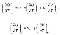
This is the partial derivative with respect to temperature taken from the internal energy value.
48. Continuity equation
According to the gas flow theory, the gas flow in the case of stationarity is determined using a special system of equations. It includes the following ratios:
1) energy equation for gas flow;
2) equation of state;
3) equation for the continuity of the gas flow.
Energy equation follows from the first beginning
thermodynamics for gas flows.
Continuity equation the ratio is called:
Gv = Fw.
It follows from it that in the case of steady gas flow in each section of the flow, the gas flow rate by mass is a constant value. Otherwise, this equation can be written as:
G=pFw =p 1 F 1 w 1 =P 2 F 2 w 2 =const,
Where r 1 ,r 2 , r= 1/v gas density in cross sections;
F 1, F 2– flow cross-sectional area;
w 1, w 2– flow velocity, measured in the cross-sectional area.
In this case, there are two flow sections (1st and 2nd), and the value G from this equation is called gas mass flow rate (per second).
As you know, Newton’s second law states: “Force is determined by the product of mass and acceleration.” If the gas flow is one-dimensional, then the second law follows:
In this relationship, each term has a specific physical meaning. Let's look at each factor in the equation.
1. Magnitude
shows how pressure changes depending on the X-coordinate.
2. Magnitude
shows how the speed changes depending on the X-coordinate.
3. Ratio
is equal to the force applied to the elementary volume, dV is the selected volume.
4. Magnitude
gas is equal to the acceleration of mass pdV(elemental mass).
49. Pushing work
Pushing work. To determine it in the equation:
let's substitute the equality i = u + pv, we get as a result:
where d(pv) is the pushing work calculated for an elementary volume,
d(pv) = pdv+vdp– equation for elementary work.
Relationship (2), including gravitational forces, has the form:
In the case when the gas flow is represented as an adiabatic process in which dq = 0, relation (1) is written as follows:

With adiabatic flow motion, the sum of the specific kinetic energy and specific enthalpy is a constant value.
If technical work takes place in the process, then for a gas flow the first law of thermodynamics will have the form:

Where dl TEK– useful work (elementary).
50. Available work during gas outflow
Let's study the process of movement (outflow) of a gas flow.
Let us assume that there is a certain container; it contains steam or gas (i.e., a working fluid) having state parameters in the form of values f 1, v 1, p 1. From this vessel, in the wall of which there is a hole, gas flows into the environment. This occurs due to the difference in pressure (p 1 – p 2), the gas outlet has a pressure p 1< p 2 Соответственно температура газа при этом равна t2, and the specific volume is v 2 In order for the stream of escaping gas to receive a given direction, cylindrical nozzles (so-called nozzles) are placed on the outside of the vessel to the surface where the hole is located. Most often they have the shape of a truncated cone, tapering towards the outer edge. Such nozzles are called confusers. In the case of a channel operating according to the reverse process, such a nozzle is a diffuser. The mouth is the outer (i.e., exit) section of the nozzle.
Let us denote the speed of the gas jet at the exit from the mouth by the value and at the entrance to the vessel by the value W 1 (inflowing gas), while the nozzle has an orifice, the cross section of which is determined by the area f. In practice w 1 much less w2, When calculating, it is neglected and accepted: w 1= 0, w 2= w.

dq = du + dA,
Where dA = pdv – expansion work, or elementary work done by the gas itself. From here:
Thus, as a result of the outflow of gas, we have work equal to A 0 . Numerically, it is equal to either the increase in kinetic energy during the outflow, or the sum of the work of pushing and against external forces.
51. Outflow velocity in a tapering channel, mass flow velocity
Outflow velocity in a tapering channel
Let us consider the process of adiabatic outflow of matter. Let us assume that a working fluid with a certain specific volume (v 1) is in a tank under a certain pressure (p 1). The outflow process involves the movement of gas (or vapor) from a medium under pressure p 1(reservoir) into the environment, the pressure in which p2< p 1 . At the same time, during the process of flow of the working substance from the nozzle, the pressure inside the tank practically does not decrease; this is acceptable in the case of a very large tank volume. When a gas (steam) flow moves through a nozzle, its potential energy is very small and its change is usually neglected. In this case, the kinetic energy increases.

Where w 1– speed of movement of the substance flow in the inlet section of the nozzle;
w 2– speed at the nozzle exit.
gas (steam) flow rate from the nozzle.
Most often speed w 1 much less speed w 2(W1 << W2), therefore it is neglected and considered W 1 = 0.
Mass flow velocity the relation is called:

Where G c– second consumption of steam (gas);
S – flow cross-sectional area;
r– density of the working fluid.

52. Outflow of droplet liquid. Mass flow
The available work for any substance that is a working fluid is determined by the formula:
I 0 = q +(i 1 – i 2).
If the flow is adiabatic (at q= 0)

Where i– enthalpy (J/kg);
W2 = w– outflow velocity (m/s).
The quantity Di = i 1 – i 2, equal to the enthalpy difference, is called heat loss of gas (steam).

and for a droplet liquid the following equality holds:
Where w– speed of fluid flow from the nozzle.
Mass flow is the amount of substance that flows through the nozzles per second. It is equal to the ratio of the second volume of outflow of a substance (gas) U2 to the specific volume of the same substance corresponding to the pressure p2:

mass flow (it is also determined from the continuity equation: Gv = Sw).
53. Critical speed
Analysis of the formula for the outflow velocity shows that as the value of p 2 /p 1 decreases, the flow velocity increases. This is possible, for example, if pi = const and the pressure p2 decreases.
It is known from experiments that the pressure at the outlet of a convergent nozzle (or a nozzle of constant cross-section) p 2 can be reduced only to a certain limiting value, the so-called critical pressure (p critical). At the same time critical pressure ratio is called the quantity b= p critical /p 1, hence P k = bp 1
As a result of a decrease in pressure p 0 (external environment) at p 1= const two cases are possible:
1) p o >= P k, i.e., while the pressure p o decreases to a critical value, the equality is observed p2= p o where p 2 is the pressure of the substance at the outlet of the convergent nozzle, p o is the pressure of the external environment;
2) p o< P к, т. е. дальнейшее падение давления p o среды ниже критического значения определяется равенством p 2 = pk, and the pressure p 2 of the flowing substance is constant (p2= const).
Thus, the phenomenon in which the pressure at the mouth of the nozzle is constant and does not decrease is called by closing the nozzle. Therefore, such pressure at the nozzle outlet, which cannot be lowered by reducing the pressure of the external environment into which the working fluid flows, is called critical(P 2k).
Regardless of the drop in ambient pressure p o at the mouth of the convergent nozzle at b k pressure P 2k is set = const, which corresponds to G max = const (mass flow), w k= const (expiration speed), Tk= const (temperature), and v 2 k= const (specific volume), i.e. the constancy of all parameters at the nozzle exit (the so-called output parameters).
In the resulting formulas, a, Y are coefficients determined only by the value k(adiabatic exponent), their values are found from special tables.
By definition critical speed is called the highest speed of a substance when it flows out of a nozzle, not exceeding the speed of sound, i.e. w k =a, Where A– the so-called local speed of sound.
The resulting formula is called Laplace's equation.
54. Flow of an ideal gas through a combined Laval nozzle
Laval nozzles are used to create a supercritical process of outflow of the working fluid, the condition of which is p o /p 1 < b k В нем выделяют три основные области.
1. A tapering short part in which the flow velocity is subsonic.
2. A narrow section in which matter moves at the speed of sound.
3. Expanding cone-shaped nozzle (supersonic flow speed).
The main condition for choosing the dimensions of the wide part of the Laval nozzle for the outflow of the working fluid is its continuity from the walls of the nozzle. Therefore, the cone opening angle should have a limit of 12 o, this helps eliminate significant losses due to gas (steam) expansion.
Let us consider the processes occurring during the operation of a combined nozzle. In the case when the external pressure p o< pk, the flow speed and pressure in the narrow plane of the nozzles are critical.
The design of the Laval nozzle allows for each ratio o< p o/p 1< b obtain complete expansion of the substance within the limits of the pressure value. In this case, no energy is lost in the outlet section of the nozzle, and when the pressure of the working fluid and the external environment is equalized, the flow speed becomes supersonic, which is necessary for the use of the nozzle in practice. In this case, the mass flow rate becomes maximum; its value depends on the area of the smallest cross-section of the nozzle (S min).
In the narrow part of the nozzle (called the neck), critical values of the parameters V k, T k, p k, w k = w sound, G max are established (where W sound is the local speed of sound). The movement of the flow along the expanding part is characterized by the fact that the gas expands further within the boundaries [p 2k, p 1], the speed increases in the interval (i.e., to values w> W sound), which leads to a decrease in pressure, but at the same time the specific volume increases (i.e. v>v k , p< p k).
The expanding part of the nozzle can serve as a diffuser if in a narrow plane w< w зв (для p o / p 1 > b k).
55. Gas throttling and process equation
For water vapor the critical temperature is T k= 647 K, respectively, T inv> 4400 K (inversion temperature). IN throttling process Cooling of water vapor always occurs; this is due to the complete dissociation of vapor molecules at such not very high values of a given inversion temperature.
Throttling of water vapor is characterized by the following properties obtained from the analysis of diagram (i, s):
1) for any state of steam, throttling always lowers the temperature of the water vapor;
2) throttling of wet vapors at low pressures is accompanied by a transition from a humidified to a dry, and then to a superheated state. Wet vapors at high pressures are first further moistened, but then also form a dry and superheated phase;
3) throttling of superheated vapors at high pressures (if the superheating temperature is low) is accompanied by their passage through several phases (dry saturated, wet, dry and finally, superheated). The last state of steam is characterized by low temperatures and pressures. In general, during throttling, superheated vapors retain their superheated state if their pressures were high at the beginning of the process.
Typically, on an is-diagram, the throttling process i 1 = i 2 is a horizontal line directed towards increasing entropy (due to the irreversibility of the process).
It is known that the pressure of superheated steam (and its useful work) decreases during the crushing process.
and hell< a дрос, где а дрос - температурный эффект адиабатного необратимого расширения (т. е. дросселирования), а а ад – эффект адиабатного обратимого расширения. Отсюда при одном давлении dp we have:
dT dros< dT ад на величину v/cp.

56. Heat transfer through a spherical wall
Let there be a hollow ball with internal and external radii, respectively r 1 and r 2, thermal conductivity coefficient I which is constant. For given boundary conditions of the third kind, the heat transfer coefficients on the surfaces of the ball will also be determined a 1 And a 2 and temperatures of the internal and external environments, respectively, Tl 1 and Tl 2. Odds a 1 ,a 2 will be constant in time, and the temperatures Tl 1, Tl 2 will be constant both in time and over the surfaces.
In a stationary heat transfer mode, the total heat flux Q transferred through a uniform spherical wall from a hot medium to a cold medium will be constant for all isothermal surfaces and can be determined by three equations.

where d 1 ,d 2 – internal and external diameters of the ball;
a 1 ,a 2 heat transfer coefficients from the hot medium to the wall and from the wall to the cold medium;
I– coefficient of thermal conductivity of the wall material;
T 1, T 2 – temperatures of the inner and outer walls.
where DT = Tzh 1 – Tzh 2 – total temperature difference;
K sh– heat transfer coefficient of the spherical wall (W/deg).