Electromagnetic oscillations oscillatory circuit. Oscillatory circuit
Consider the following oscillatory circuit. We will assume that its resistance R is so small that it can be neglected.
Full electromagnetic energy oscillatory circuit at any time will be equal to the sum of the energy of the capacitor and the energy magnetic field current. The following formula will be used to calculate it:
W = L*i^2/2 + q^2/(2*C).
The total electromagnetic energy will not change over time, since there is no energy loss through the resistance. Although its components will change, in total they will always give same number. This is ensured by the law of conservation of energy.
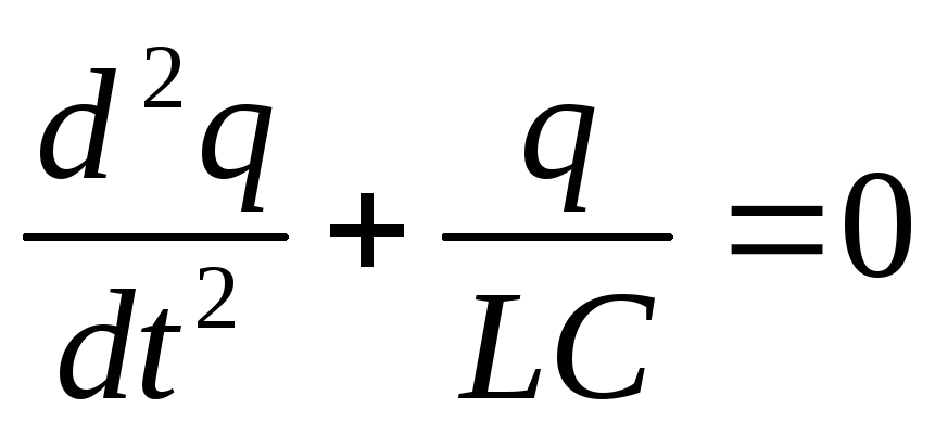
From this we can obtain equations describing free oscillations in an electric oscillatory circuit. The equation will look like this:
q"’ = -(1/(L*C))*q.
The same equation, up to notation, is obtained when describing mechanical vibrations. Considering the analogy between these types of oscillations, we can write down a formula describing electromagnetic oscillations.
Frequency and period of electromagnetic oscillations
But first, let's look at the frequency and period of electromagnetic oscillations. The value of the frequency of natural vibrations can again be obtained from an analogy with mechanical vibrations. The coefficient k/m will be equal to the square of the natural oscillation frequency.
Therefore, in our case the square frequencies free oscillations will be equal to 1/(L*C)
ω0 = 1/√(L*C).
From here period free vibrations:
T = 2*pi/ω0 = 2*pi*√(L*C).
This formula is called Thompson's formulas. It follows from this that the oscillation period increases with increasing capacitance of the capacitor or inductance of the coil. These conclusions are logical, since with an increase in capacitance, the time spent charging the capacitor increases, and with an increase in inductance, the current strength in the circuit will increase more slowly, due to self-induction.
Charge Oscillation Equation capacitor is described by the following formula:
q = qm*cos(ω0*t), where qm is the amplitude of oscillations of the capacitor charge.
The current strength in the oscillatory circuit circuit will also perform harmonic oscillations:
I = q’= Im*cos(ω0*t+pi/2).
Here Im is the amplitude of current fluctuations. Note that between the oscillations of charge and current strength there is a difference in vases equal to pi/2.
The figure below shows graphs of these fluctuations.
Again, by analogy with mechanical vibrations, where fluctuations in the speed of a body are ahead of fluctuations in the coordinates of this body by pi/2.
In real conditions, the resistance of the oscillatory circuit cannot be neglected, and therefore the oscillations will be damped.
With a very high resistance R, oscillations may not begin at all. In this case, the energy of the capacitor is released in the form of heat at the resistance.
Free electromagnetic oscillations These are periodic changes in the charge on the capacitor, the current in the coil, as well as electric and magnetic fields in the oscillatory circuit that occur under the influence of internal forces.
Continuous electromagnetic oscillations
To excite electromagnetic oscillations it is used oscillatory circuit , consisting of an inductor L connected in series and a capacitor with capacitance C (Fig. 17.1).
Let's consider an ideal circuit, i.e. a circuit whose ohmic resistance is zero (R=0). To excite oscillations in this circuit, it is necessary either to impart a certain charge to the capacitor plates, or to excite a current in the inductor. Let at the initial moment of time the capacitor be charged to a potential difference U (Fig. (Fig. 17.2, a); therefore, it has potential energy  .At this moment in time, the current in the coil I = 0 .
This state of the oscillatory circuit is similar to the state of a mathematical pendulum, deflected by an angle α (Fig. 17.3, a). At this time, the current in the coil is I=0. After connecting a charged capacitor to the coil, under the influence of the electric field created by the charges on the capacitor, free electrons in the circuit will begin to move from the negatively charged plate of the capacitor to the positively charged one. The capacitor will begin to discharge, and an increasing current will appear in the circuit. The alternating magnetic field of this current will generate an electric vortex. This electric field will be directed opposite to the current and therefore will not allow it to immediately reach its maximum value. The current will increase gradually. When the force in the circuit reaches its maximum, the charge on the capacitor and the voltage between the plates are zero. This will happen after a quarter of the period t = π/4. At the same time, the energy e
.At this moment in time, the current in the coil I = 0 .
This state of the oscillatory circuit is similar to the state of a mathematical pendulum, deflected by an angle α (Fig. 17.3, a). At this time, the current in the coil is I=0. After connecting a charged capacitor to the coil, under the influence of the electric field created by the charges on the capacitor, free electrons in the circuit will begin to move from the negatively charged plate of the capacitor to the positively charged one. The capacitor will begin to discharge, and an increasing current will appear in the circuit. The alternating magnetic field of this current will generate an electric vortex. This electric field will be directed opposite to the current and therefore will not allow it to immediately reach its maximum value. The current will increase gradually. When the force in the circuit reaches its maximum, the charge on the capacitor and the voltage between the plates are zero. This will happen after a quarter of the period t = π/4. At the same time, the energy e 
 electric field transforms into magnetic field energyW e =1/2C U 2 0. At this moment, there will be so many electrons transferred to it on the positively charged plate of the capacitor that their negative charge completely neutralizes the positive charge of the ions present there. The current in the circuit will begin to decrease and the induction of the magnetic field it creates will begin to decrease. The changing magnetic field will again generate an electric vortex, which this time will be directed in the same direction as the current. The current supported by this field will flow in the same direction and gradually recharge the capacitor. However, as charge accumulates on the capacitor, its own electric field will increasingly inhibit the movement of electrons, and the current strength in the circuit will become less and less. When the current drops to zero, the capacitor will be completely overcharged.
The system states shown in Fig. 17.2 and 17.3, correspond to successive moments in time T
= 0;
 ;
; ;
; And T.
The self-inductive emf arising in the circuit is equal to the voltage on the capacitor plates: ε = U
 And
And 

Believing  , we get
 (17.1)
Formula (17.1) is similar to the differential equation of harmonic vibration considered in mechanics; his decision will be
q = q max sin(ω 0 t+φ 0) (17.2)
where q max is the largest (initial) charge on the capacitor plates, ω 0 is the circular frequency of the circuit’s natural oscillations, φ 0 is the initial phase.
According to the accepted notation,  where
where
 (17.3)
Expression (17.3) is called Thomson's formula and shows that when R=0, the period of electromagnetic oscillations arising in the circuit is determined only by the values of inductance L and capacitance C.
According to the harmonic law, not only the charge on the capacitor plates changes, but also the voltage and current in the circuit:
where U m and I m are the amplitudes of voltage and current.
From expressions (17.2), (17.4), (17.5) it follows that the oscillations of charge (voltage) and current in the circuit are phase shifted by π/2. Consequently, the current reaches its maximum value at those moments in time when the charge (voltage) on the capacitor plates is zero, and vice versa.
When a capacitor is charged, an electric field appears between its plates, the energy of which
 or
or 
When a capacitor is discharged onto an inductor, a magnetic field arises in it, the energy of which

In an ideal circuit, maximum energy electric field equal to the maximum magnetic field energy:

The energy of a charged capacitor periodically changes over time according to the law
 or
or 
Considering that  , we get

The energy of the magnetic field of the solenoid changes with time according to the law
 (17.6)
Considering that I m =q m ω 0, we obtain
 (17.7)
The total energy of the electromagnetic field of the oscillatory circuit is equal to
W =W e +W m = (17.8)
In an ideal circuit, the total energy is conserved and the electromagnetic oscillations are undamped.
Damped electromagnetic oscillations
 A real oscillatory circuit has ohmic resistance, so the oscillations in it are damped. In relation to this circuit, we write Ohm's law for the complete circuit in the form
 (17.9)
Transforming this equality:

and making the replacement:
 And
And  ,where β-damping coefficient we get
 (10.17) - this is differential equation of damped electromagnetic oscillations
.
(10.17) - this is differential equation of damped electromagnetic oscillations
.
The process of free oscillations in such a circuit no longer obeys the harmonic law. For each period of oscillation, part of the electromagnetic energy stored in the circuit is converted into Joule heat, and the oscillations become fading(Fig. 17.5). For small attenuations ω ≈ ω 0, the solution to the differential equation will be an equation of the form
 (17.11)
Damped oscillations in an electrical circuit are similar to damped mechanical oscillations of a load on a spring in the presence of viscous friction.
The logarithmic damping decrement is equal to
 (17.12)
Time interval  during which the amplitude of oscillations decreases by e ≈ 2.7 times is called decay time
.
during which the amplitude of oscillations decreases by e ≈ 2.7 times is called decay time
.
Quality factor Q of the oscillatory system determined by the formula:
 (17.13)
For an RLC circuit, the quality factor Q is expressed by the formula
 (17.14)
The quality factor of electrical circuits used in radio engineering is usually on the order of several tens or even hundreds.
Charge the capacitor from the battery and connect it to the coil. In the circuit we created, electromagnetic oscillations will immediately begin (Fig. 46). The discharge current of the capacitor, passing through the coil, creates a magnetic field around it. This means that during the discharge of a capacitor, the energy of its electric field transforms into the energy of the magnetic field of the coil, just as when a pendulum or string oscillates, potential energy transforms into kinetic energy.
As the capacitor discharges, the voltage across its plates drops and the current in the circuit increases, and by the time the capacitor is completely discharged, the current will be maximum (current amplitude). But even after the end of the capacitor discharge, the current will not stop - the decreasing magnetic field of the coil will maintain the movement of charges, and they will again begin to accumulate on the capacitor plates. In this case, the current in the circuit decreases, and the voltage across the capacitor increases. This process of the reverse transition of the energy of the magnetic field of the coil into the energy of the electric field of the capacitor is somewhat reminiscent of what happens when the pendulum, having passed the midpoint, rises upward.
By the time the current in the circuit stops and the magnetic field of the coil disappears, the capacitor will be charged to the maximum (amplitude) voltage of reverse polarity. The latter means that on the plate where there were previously positive charges, there will now be negative ones, and vice versa. Therefore, when the discharge of the capacitor begins again (and this will happen immediately after it is fully charged), a current in the opposite direction will flow in the circuit.
The periodically repeated exchange of energy between the capacitor and the coil represents electromagnetic oscillations in the circuit. During these oscillations, an alternating current flows in the circuit (that is, not only the magnitude, but also the direction of the current changes), and an alternating voltage acts on the capacitor (that is, not only the voltage magnitude changes, but also the polarity of the charges accumulating on the plates). One of the directions of current voltage is conventionally called positive, and the opposite direction is called negative.
By observing changes in voltage or current, you can build a graph of electromagnetic oscillations in the circuit (Fig. 46), just as we built a graph of mechanical oscillations of a pendulum (). On a graph, positive current or voltage values are plotted above the horizontal axis, and negative currents or voltages are plotted below this axis. That half of the period when the current flows in the positive direction is often called the positive half-cycle of the current, and the other half - the negative half-cycle of the current. We can also talk about positive and negative half-cycle voltage.
I would like to emphasize once again that we use the words “positive” and “negative” completely conditionally, only to distinguish two opposite directions of current.
The electromagnetic oscillations we have become familiar with are called free or natural oscillations. They occur whenever we transfer a certain amount of energy to the circuit, and then allow the capacitor and coil to freely exchange this energy. The frequency of free oscillation (that is, the frequency of the alternating voltage and current in the circuit) depends on how quickly the capacitor and coil can store and release energy. This, in turn, depends on the inductance Lk and capacitance Ck of the circuit, just as the frequency of vibration of a string depends on its mass and elasticity. The greater the inductance L of the coil, the longer it takes to create a magnetic field in it, and the longer this magnetic field can maintain current in the circuit. The larger the capacitance C of the capacitor, the longer it will take to discharge and the longer it will take for this capacitor to recharge. Thus, the more Lk and Ck of the circuit, the slower the electromagnetic oscillations occur in it, the lower their frequency. The dependence of the frequency f o of free oscillations on L to and C to the circuit is expressed by a simple formula, which is one of the basic formulas of radio engineering:

The meaning of this formula is extremely simple: in order to increase the frequency of natural oscillations f 0, you need to reduce the inductance L k or the capacitance C k of the circuit; to reduce f 0, inductance and capacitance must be increased (Figure 47).

From the formula for frequency one can easily derive (we have already done this with the formula of Ohm’s law) calculation formulas for determining one of the parameters of the circuit L k or C k at a given frequency f0 and a known second parameter. Formulas convenient for practical calculations are given on sheets 73, 74 and 75.

ELECTROMAGNETIC OSCILLATIONS AND WAVES
§1 Oscillatory circuit.
Natural vibrations in an oscillatory circuit.
Thomson's formula.
Decaying and forced oscillations in k.k.
- Free oscillations in k.k.
An oscillating circuit (OC) is a circuit consisting of a capacitor and an inductor. Under certain conditions in the k.k. Electromagnetic fluctuations of charge, current, voltage and energy may occur.
 Consider the circuit shown in Fig. 2. If you put the key in position 1, the capacitor will charge and a charge will appear on its platesQ and voltage U C. If you then move the key to position 2, the capacitor will begin to discharge, current will flow in the circuit, and the energy of the electric field contained between the plates of the capacitor will be converted into magnetic field energy concentrated in the inductorL. The presence of an inductor leads to the fact that the current in the circuit does not increase instantly, but gradually due to the phenomenon of self-induction. As the capacitor discharges, the charge on its plates will decrease, and the current in the circuit will increase. Maximum value the loop current will reach zero when the charge on the plates is equal to zero. From this moment, the loop current will begin to decrease, but, due to the phenomenon of self-induction, it will be supported by the magnetic field of the inductor, i.e. When the capacitor is completely discharged, the energy of the magnetic field stored in the inductor will begin to transform into the energy of the electric field. Due to the loop current, the capacitor will begin to recharge and a charge opposite to the original one will begin to accumulate on its plates. The capacitor will be recharged until all the energy of the magnetic field of the inductor is converted into the energy of the electric field of the capacitor. Then the process will be repeated in the opposite direction, and thus electromagnetic oscillations will arise in the circuit.
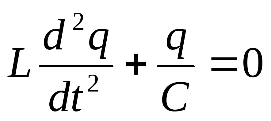
Let us write Kirchhoff’s 2nd law for the considered k.k.,
Differential equation k.k.
We have obtained the differential equation for charge oscillations in the k.k. This equation is similar to the differential equation describing the motion of a body under the action of a quasi-elastic force. Consequently, the solution to this equation will be written similarly
![]()
Equation of charge oscillations in k.k.
![]()
Equation of voltage oscillations on the capacitor plates in the s.c.c.
![]()
Equation of current oscillations in a c.c.
- Damped oscillations in k.k.
Consider a CC containing capacitance, inductance and resistance. Kirchhoff's 2nd law in this case will be written in the form
![]()
- attenuation coefficient,
Natural cyclic frequency.
![]()
- - differential equation of damped oscillations in the k.k.
![]()
Equation of damped oscillations of a charge in a c.c.
The law of change in charge amplitude during damped oscillations in a c.c.;

Period of damped oscillations.
![]()
Decrement of attenuation.

- logarithmic damping decrement.

Contour quality factor.
If the attenuation is weak, then T ≈T 0
Let's study the change in voltage on the capacitor plates.![]()
![]()
The change in current differs in phase by φ from the voltage.
![]()
at - damped oscillations are possible,
at - critical position
![]()

at , i.e. R >
RTO- oscillations do not occur (aperiodic capacitor discharge).
>> Equation describing processes in an oscillatory circuit. Period of free electrical oscillations
§ 30 EQUATION DESCRIBING PROCESSES IN AN OSCILLATING CIRCUIT. PERIOD OF FREE ELECTRICAL OSCILLATIONS
Let us now move on to the quantitative theory of processes in an oscillatory circuit.
An equation describing processes in an oscillatory circuit. Let's consider an oscillatory circuit whose resistance R can be neglected (Fig. 4.6).
The equation that describes free electrical oscillations in a circuit can be obtained using the law of conservation of energy. The total electromagnetic energy W of the circuit at any time is equal to the sum of its magnetic and electric field energies:
![]()
This energy does not change over time if the resistance R of the circuit is zero. This means that the time derivative of the total energy is zero. Consequently, the sum of the time derivatives of the energies of the magnetic and electric fields is equal to zero:

The physical meaning of equation (4.5) is that the rate of change of magnetic field energy in absolute value is equal to the rate of change of electric field energy; The "-" sign indicates that when the electric field energy increases, the magnetic field energy decreases (and vice versa).
Having calculated the derivatives in equation (4.5), we obtain 1
But the derivative of charge with respect to time is the current in at the moment time:
Therefore, equation (4.6) can be rewritten as follows:
1 We calculate derivatives with respect to time. Therefore, the derivative (i 2)" is not simply equal to 2 i, as it would be when calculating the derivative but i. It is necessary to multiply 2 i by the derivative i" of the current strength over time, since the derivative of a complex function is being calculated. The same applies to the derivative (q 2)."
The derivative of current strength with respect to time is nothing more than the second derivative of charge with respect to time, just as the derivative of speed with respect to time (acceleration) is the second derivative of coordinates with respect to time. Substituting i" = q" into equation (4.8) and dividing the left and right sides of this equation by Li, we obtain the basic equation describing free electrical oscillations in the circuit:

Now you're in to the fullest you can appreciate the value of the efforts that were expended to study the oscillations of a ball on a spring and a mathematical pendulum. After all, equation (4.9) is no different, except for notation, from equation (3.11), which describes the oscillations of a ball on a spring. When replacing x in equation (3.11) with q, x" with q", k with 1/C and m with L, we exactly obtain equation (4.9). But equation (3.11) has already been solved above. Therefore, knowing the formula that describes the oscillations of a spring pendulum, we can immediately write down a formula to describe the electrical oscillations in the circuit.
Lesson content lesson notes supporting frame lesson presentation acceleration methods interactive technologies Practice tasks and exercises self-test workshops, trainings, cases, quests homework discussion questions rhetorical questions from students Illustrations audio, video clips and multimedia photographs, pictures, graphics, tables, diagrams, humor, anecdotes, jokes, comics, parables, sayings, crosswords, quotes Add-ons abstracts articles tricks for the curious cribs textbooks basic and additional dictionary of terms other Improving textbooks and lessonscorrecting errors in the textbook updating a fragment in a textbook, elements of innovation in the lesson, replacing outdated knowledge with new ones Only for teachers perfect lessons calendar plan for the year methodological recommendations discussion programs Integrated Lessons